
Every solar panel runs two parallel processes simultaneously. One is photovoltaic conversion. The other is heating. The second process degrades the first. A silicon cell rated at 20 percent efficiency at 25 degrees Celsius loses roughly 0.45 percent of that efficiency for every degree it heats beyond that number. On a summer afternoon in a high-sun location, a panel surface can reach 65 degrees. The arithmetic takes three seconds: 40 degrees above the rating point, multiplied by 0.45 percent per degree, is 18 percent of rated power consumed by the heat the cell generated by failing to convert the infrared that caused it.
The Dynamic Liquid Crystal Energy Converter starts from a different premise. If the cell cannot use certain wavelengths, it should not receive them. The front surface of the panel becomes an active optical system, sorting incoming light before it reaches the absorbers, routing useful wavelengths toward the cells best matched for them and directing everything else away from anything heat-sensitive. The sorting mechanism is a set of tunable liquid crystal layers. The control signal driving them is a low-voltage electrical input that recalibrates continuously as the sun moves and the spectrum shifts.
The short version: A Dynamic Liquid Crystal Energy Converter places tunable cholesteric liquid crystal layers in front of the photovoltaic cells, using their ability to selectively reflect specific wavelengths to route infrared away from silicon cells and toward a secondary absorber matched to that band. The system adjusts its spectral configuration electrically as the sun moves, without mechanical parts. Efficiency gains over equivalent static panels reach between 18 and 35 percent depending on location and configuration.
Key Takeaways
- The liquid crystal layers generate no electricity themselves – they act as a programmable optical sorting system, and the sorting is the entire source of the gain
- Cholesteric liquid crystals reflect specific wavelengths because their helical molecular structure creates a periodic optical resonance, and that resonance shifts when voltage is applied
- The device tracks the changing spectral composition of sunlight through the day electrically, with no moving parts and no mechanical failure modes
- Agricultural deployments route infrared to energy absorbers while passing photosynthetically active light through to crops below – the same surface harvesting power and feeding plants at the same time
- At building scale, coordinated panels operating as a network function as a single distributed light-management system, not a collection of independent converters
Table of Contents
What a Standard Panel Does With the Spectrum It Receives
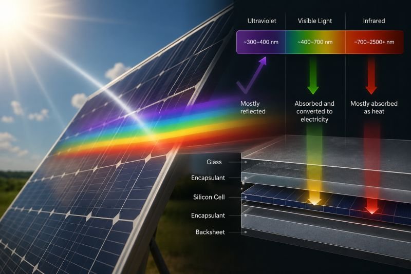
Sunlight arriving at a photovoltaic surface is not a single thing. It covers a continuous distribution of wavelengths from roughly 300 nanometers in the ultraviolet to beyond 2500 nanometers in the thermal infrared, with each band carrying a different fraction of the total energy. At sea level under clear sky conditions, approximately 5 percent of that energy arrives as ultraviolet, 43 percent as visible light, and 52 percent as infrared. A silicon photovoltaic cell responds efficiently to the visible band and a portion of the near-infrared. The rest either heats the cell or reflects off the surface without doing any work.
This distribution is not a design flaw in silicon. It follows directly from the bandgap, the minimum photon energy required to excite an electron across the junction. Photons below this threshold pass through or warm the material. Photons above it lose their surplus energy as heat inside the cell. The cell has a fixed optical appetite, and the sun delivers far more than that appetite covers.
The Wavelengths a Silicon Cell Cannot Reach
The thermal infrared – wavelengths from roughly 1400 nanometers upward – carries more than 20 percent of total solar energy at ground level. Silicon cannot convert it. What it does instead is absorb part of it as heat, and that absorbed heat drives the temperature rise that reduces the efficiency of the visible-band conversion the cell was built to perform. One problem feeds the other.
Near-infrared between 700 and 1400 nanometers sits in an intermediate zone where silicon has some response, but not efficient conversion. Multi-junction cells address this with layers tuned to different bands, but multi-junction fabrication is expensive and brittle, which is why single-junction silicon still dominates deployed installations. The optical management problem – controlling what wavelengths reach the cell in the first place – has attracted less attention than cell-material improvement, largely because the front surface was always treated as a passive structural component rather than an active participant in energy collection.
What Changes When the Front Surface Becomes Active
A panel that manages its own front surface is no longer a passive collector. It is a system with an input stage – one that can be optimized independently of the cell beneath it. The cell material, bandgap, and internal architecture remain fixed. What changes is the spectral profile of the light arriving at it. The dynamic liquid crystal layer is that input stage. It does not improve the cell. It improves what the cell sees.
Cholesteric Layers and How the Wavelength Gate Works
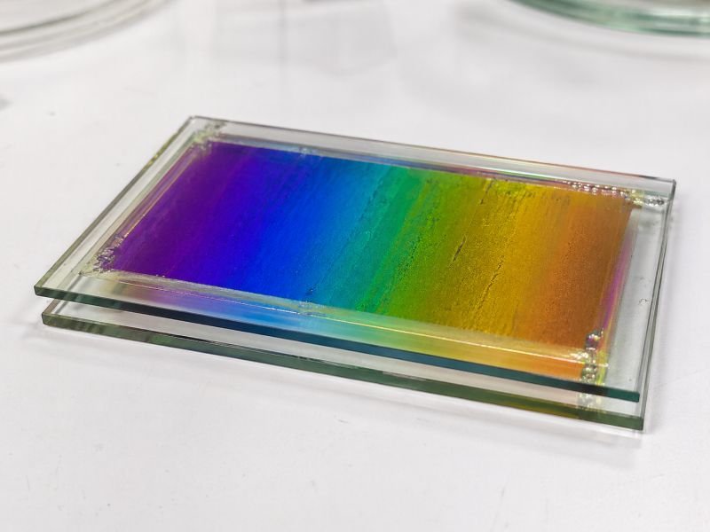
Liquid crystals occupy a physical state between solid and liquid, where molecules maintain orientational order without fixed positional arrangement. In cholesteric phases, that order takes a helical form: each molecular layer is rotated slightly relative to the one below it, producing a continuous spiral through the material’s depth.
The optical consequence of this structure is specific and useful. When the pitch of the helix – the distance required for one complete 360-degree rotation of molecular orientation – matches the wavelength of incoming light, that wavelength encounters a periodic refractive index variation tuned to its frequency. The result is strong selective reflection. Neighboring wavelengths with different frequencies pass through with minimal attenuation. The material acts as a narrow-band mirror targeting a single spectral region while remaining transparent to everything else.
Adjusting the Mirror by Changing the Pitch
The pitch of a cholesteric helix is not fixed. Applying a voltage across the layer alters the molecular orientation and changes the pitch. Different voltages produce different reflected wavelengths. The tuning range for purpose-designed cholesteric materials covers several hundred nanometers, spanning from near-ultraviolet through visible and into the near-infrared. Reflection bandwidth for a single layer is typically 50 to 150 nanometers wide. Stacking multiple layers with slightly offset pitches broadens the effective gate and allows a device to manage distinct spectral regions with separate control signals.
The reflection efficiency of a well-constructed cholesteric layer exceeds 95 percent at its target wavelength. Transmission losses at off-target wavelengths stay below 5 percent. Operating voltage runs between 1 and 5 volts, consuming power at the milliwatt level per square meter of active surface. Against the watts-per-square-meter gain from spectral optimization, the control power budget is negligible.
Nematic Layers and Thermotropic Alternatives
Cholesteric liquid crystals handle the selective spectral reflection function. Nematic liquid crystals – where molecules align in parallel without helical twist – serve a different role in the stack: they function as broadband transmission switches, able to toggle regions of the active surface between high and low transmittance states. Together, they give the device a two-tier control system: fine spectral selection through the cholesteric layer, and coarser zone management through the nematic layer.
Thermotropic liquid crystals offer a third configuration. These materials change their phase and optical properties in response to temperature rather than applied voltage. A thermotropic layer designed to shift its reflection peak as the panel heats up creates a passive feedback loop. As infrared loading increases and the panel warms, the layer automatically redirects more of the infrared band away from heat-sensitive cells. When irradiance drops, the layer relaxes its redirection. No controller, no sensors, no external power – the material responds directly to the physical condition it manages.
How the Dynamic Liquid Crystal Energy Converter Could Operate
A full converter is a layered stack built around two separate photovoltaic absorbers and two distinct liquid crystal control layers. Moving from the front surface inward: the cholesteric management layer, a photovoltaic absorber optimized for visible wavelengths, a secondary LC routing layer, and a photovoltaic absorber with a bandgap matched to the near-infrared band. The stack is sealed within a frame containing thermal channels and a microcontroller receiving real-time readings from both cells, an ambient temperature sensor, and a solar position model.
The Spectral Sorting Sequence
Sunlight arrives at the front cholesteric layer. The controller has set the layer’s pitch to reflect wavelengths above approximately 750 nanometers – the near-infrared load – back away from the surface and toward a concentrating reflector channel at the frame edge, where a thermal or photovoltaic absorber waits for them. The visible band passes through the cholesteric layer with losses under 5 percent and reaches the first cell, where it is converted at that cell’s rated efficiency.
Light that the visible-band cell cannot convert – long-wavelength near-infrared that passed through the front layer – hits the secondary LC layer. That layer routes the 800-to-1400 nanometer band toward the secondary photovoltaic absorber, which uses materials with a bandgap set for that range. Both cells generate independently and feed a shared DC bus.
Electrical Tracking Without Moving Parts
As the sun moves from east to west, the spectral composition of direct sunlight changes. The proportion of short-wavelength visible light peaks at solar noon, when the light travels through the least atmosphere. The near-infrared component fluctuates with atmospheric water vapor and aerosol loading. In the morning and late afternoon, the light path through the atmosphere is longer, and shorter wavelengths scatter out – the spectrum arriving at the panel shifts toward red and infrared.
The LC control system compensates by adjusting layer voltages in response to the arriving spectral distribution rather than purely to a geometric solar position model. The reorientation of the molecular layers takes milliseconds. No gears move. No actuators extend. The adaptation is entirely electrical.
Thermotropic Mode for Passive Deployments
Electrically controlled stacks require power, control hardware, and sensor infrastructure. For deployments where that infrastructure is unavailable or undesirable – isolated agricultural installations, flexible rollable surfaces deployed in remote locations, building-integrated glazing without active building management systems – the thermotropic configuration provides most of the thermal management benefit without the complexity.
A thermotropic stack designed around two phase-transition temperatures – one triggering increased IR reflection at the temperature where thermal degradation becomes significant, one relaxing the reflection when the panel cools – creates a self-regulating device. The performance is not as precise as voltage-controlled tuning, but the manufacturing and maintenance profiles are substantially simpler.
Everything here is free. Readers are the reason it stays that way.
I make all of it alone, with no ads. If it is worth a coffee a month to you, that keeps the next one coming.
Keep it alive →Splitting the Spectrum Before It Reaches the Cell
The most direct efficiency argument for the Dynamic Liquid Crystal Energy Converter comes from combining two effects that compound: reducing cell operating temperature and adding energy recovery from a band the primary cell cannot use. A formula makes the relationship concrete.
The power recovered from temperature reduction alone follows the silicon temperature coefficient:
P_recovered = ΔT × β × P_rated
Where ΔT is the temperature reduction achieved in degrees Celsius, β is the temperature coefficient of power for silicon (0.0045 per degree Celsius), and P_rated is the panel’s rated output at 25 degrees Celsius.
For a 400-watt panel held at 35 degrees by LC-managed infrared routing rather than heating to 65 degrees: ΔT = 30°C, β = 0.0045, P_rated = 400W. The calculation gives P_recovered = 30 × 0.0045 × 400 = 54 watts. That is 54 watts from temperature management alone, before the secondary IR absorber contributes anything. The IR absorber, working with a band carrying 15 to 22 percent of incident solar energy, adds a further 25 to 40 watts per square meter at standard test conditions.
| LC Type | Molecular Structure | Primary Function in Device | Control Mechanism |
|---|---|---|---|
| Cholesteric | Helical layer-by-layer rotation | Selective wavelength reflection and spectral routing | Voltage shifts helix pitch |
| Nematic | Parallel molecular alignment | Broadband transmission switching across zones | Voltage changes bulk orientation |
| Smectic | Layered parallel planes | Stable mid-range filtering in high-temperature environments | Temperature or applied field |
| Thermotropic | Phase-dependent optical state | Passive IR management without controller or sensors | Ambient temperature |
What the Numbers Mean for Building-Scale Economics
A standard building facade in a high-irradiance city might carry 200 to 500 square meters of photovoltaic surface if every viable glazed and cladding area is used. At conventional panel efficiencies, the energy yield from that area is useful but not transformative. A 30-percent efficiency gain across the same surface area closes the economic gap between facade photovoltaics and conventional rooftop installation, where orientation and tilt angle are optimized for maximum yield. The building facade moves from a marginal installation to a viable primary generation surface.
Where This Device Performs Best
Glass Facades and Building-Integrated Surfaces
A building window is an energy compromise architects have managed for decades. More glazed area means more natural light and more solar gain. More solar gain means higher cooling loads. Existing solutions – electrochromic glazing, solar control coatings, external shading – reduce unwanted solar gain without recovering energy from it. Standard photovoltaic glazing recovers energy but creates uniform visual obstruction and does not manage the thermal load intelligently.
A Dynamic Liquid Crystal window panel dissolves that tradeoff. Visible wavelengths pass through, maintaining daylight quality. Near-infrared is routed to absorbers at the frame edges. The cells behind the glazing operate at controlled temperature. The building occupants receive natural light. The facade generates electricity. The cooling plant receives a reduced load from a surface that used to be a source of gain. All three outcomes occur simultaneously from the same physical layer.
For large commercial buildings where facade area is significant and cooling energy costs are substantial, this convergence of functions makes the device economically rational without requiring any single benefit to justify the cost alone.
Agricultural Canopies and Greenhouse Structures
Plants use a specific band of the visible spectrum for photosynthesis – roughly 400 to 700 nanometers, the photosynthetically active radiation range. Wavelengths outside this band contribute little to plant growth. Infrared above the crop canopy is wasted if nothing collects it.
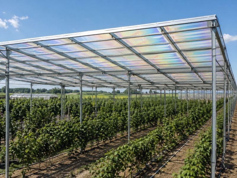
An agricultural LC converter positioned above a growing area sets its cholesteric layer to pass photosynthetically active wavelengths at near-full intensity while routing near-infrared to absorbers embedded in the canopy frame. The crops receive the light they need. The structure generates electricity from the energy they cannot use. The energy recovery does not compete with growth – it runs in parallel with it, using the part of the spectrum the plants leave untouched.
For controlled-environment agriculture, a secondary benefit compounds the primary one. Reducing near-infrared transmission through the canopy lowers interior temperature during peak summer irradiance, cutting ventilation and cooling energy loads. In winter, the thermotropic configuration shifts to allow more infrared through for passive heating. The same surface manages year-round thermal conditions while generating power throughout.
Orbital and Space Deployment
At low Earth orbit, sunlight arrives without atmospheric filtering. The full spectrum is present, including ultraviolet fractions substantially absorbed at sea level, and the infrared component is intense and continuous. Mechanical tracking systems that rotate panels toward the sun add weight, complexity, and failure modes to spacecraft that cannot be easily serviced.
An LC-based converter operating in orbit manages a spectrum richer than any ground installation encounters. The device adapts its spectral configuration to the satellite’s orbital geometry electrically, adjusting its LC layers continuously as the angle between the panel and the sun changes through each 90-minute orbit. No mechanical systems extend, rotate, or require lubrication. For large orbital structures where rigid panels with tracking mounts are impractical, flexible rollable LC converter materials – deployed from compressed storage – offer a power-to-mass ratio that fixed architectures cannot approach.
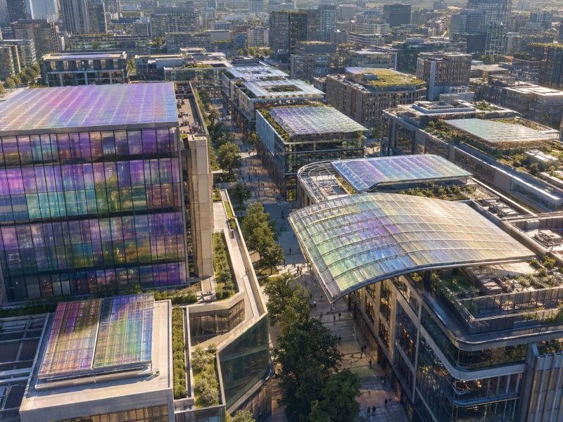
From a Single Panel to a Coordinated Light-Management Surface
A single Dynamic Liquid Crystal Energy Converter is useful. A building facade covered with them and wired to share operational data is a different kind of system entirely.
The first generation of this device is straightforward: a single panel with a two-tier LC stack, a microcontroller managing voltage inputs from local sensor readings, and output feeding a standard inverter. The physics works at this scale. The efficiency gain is real. The device functions as a better panel.
The mature generation adds coordination. Individual panels receive not just local sensor readings but shared data from neighboring panels – real-time irradiance maps across the facade, shadow tracking from adjacent structures, temperature gradients from east-facing to west-facing surfaces. Each panel’s LC configuration accounts for what the panels around it are doing. A panel entering shade shifts its spectral priorities toward diffuse sky radiation before its output begins to fall. A panel approaching peak temperature preemptively increases infrared routing intensity. The system anticipates rather than reacts.
When Panels Start Behaving Like a Single Instrument
At full building scale, coordinated panels across a facade stop functioning as independent converters. The LC adjustment patterns respond to facade-level optical conditions, not just cell-level readings. During partly cloudy conditions, when direct and diffuse irradiance are shifting across the building surface in real time, a panel network with shared data can maintain higher average efficiency than any individual optimization algorithm achieves in isolation.
The civilizational-scale form of this device is not larger panels or higher individual efficiencies. It is built surfaces – facades, canopies, glazed roofs, agricultural structures – that function as a single distributed optical instrument. The energy and the environmental sensing become the same system. A city with Dynamic Liquid Crystal surfaces at scale knows the spectral composition and intensity of sunlight across its entire exposed area continuously. That data has uses beyond energy management, and what those uses become is a question the physics of the device does not constrain.
The View From NoSuchDevice
I find the agricultural application more interesting than the building-integrated one, and not for the obvious reason. The efficiency numbers favor the high-rise facade – more surface area, controlled environments, significant cooling cost savings to offset against installation cost. The agricultural case has a smaller energy yield per unit area and a more complicated installation environment.
What makes it interesting is that it resolves a conflict that most energy technologies create rather than dissolve. Photovoltaics and food production compete for land and sunlight. A device that extracts energy specifically from the part of the spectrum plants cannot use does not compete with food production at all. The same surface does both things, and neither one degrades the other. That is a rarer property than efficiency percentage gains, and I think it matters more in the long run.
The coordinated facade concept I find harder to be enthusiastic about, not because the physics is uncertain but because buildings are messier than the physics. Panels get replaced at different times by different contractors. Facades get partially shaded by new construction. Building ownership changes. The coordination logic assumes a continuity of system integrity that real building stock does not reliably provide. The single-panel version works in the world as it is. The network version requires an institutional stability the world rarely sustains across the lifecycle of an energy installation.
On the speculative horizon, the Dynamic Liquid Crystal Energy Converter sits in an interesting position. The seed components – LCD display technology proving precision optical control at scale, cholesteric LC behavior understood in detail, multijunction photovoltaics demonstrated in lab conditions – are real. The full device as described here requires those components to mature in parallel and then be assembled into an architecture nobody has yet built. That is not a physics gap. It is an engineering gap, and engineering gaps close when someone decides they are worth closing.
Whether that moment arrives in twenty years or two hundred is a question about economics and institutional priorities, not about light.
You read the whole thing.
That is rarer than it should be, and it is the exact kind of attention I built this archive for. I make every piece alone, with no ads and no investor deciding what gets written. If you want the next machine taken apart like this one, you can help me make it.
A coffee a month is enough to keep it free for everyone.
Prefer crypto or a one time gift? Other ways to give →