There are roughly 600,000 bridges in the United States alone. A large portion of them cross rivers. Every one of those rivers moves water through city centers, industrial zones, and residential districts, 24 hours a day, without stopping. The concrete piers holding those bridges are already sitting in that current, splitting it, generating turbulence, and doing nothing with the kinetic energy flowing past every second.
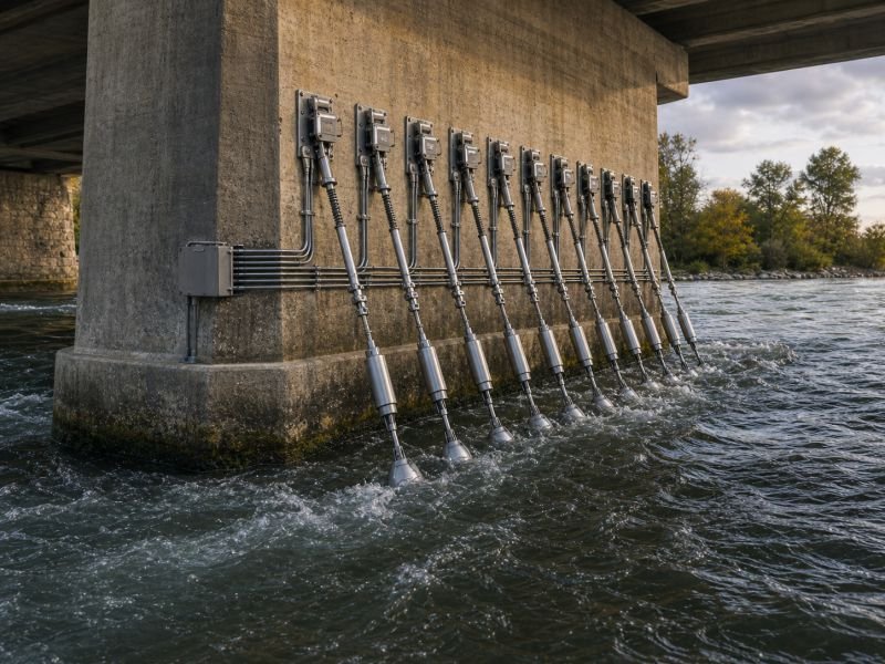
That is the premise of a concept device that lives in the overlap between civil engineering and distributed energy: a modular hydrokinetic retrofit system designed to mount onto existing urban infrastructure – bridge piers, quay walls, urban drainage channels – and extract electrical power from the flow already running through them. The river keeps moving. The bridges keep standing. The only new element is a sleeve assembly that finally does something with the energy both of them have been ignoring.
The short version: A hydrokinetic bridge retrofit is a modular turbine assembly designed to clamp onto existing urban water infrastructure without dam construction, flow diversion, or structural modification to the host structure. At river flow speeds of 1.5 to 2.5 meters per second, a single pier-mounted unit could generate between 2 and 15 kilowatts continuously. A city with 40 viable bridges over a fast urban river corridor could theoretically host a distributed network delivering hundreds of kilowatts around the clock, drawing from water already flowing and infrastructure already paid for.
Key Takeaways
- The device extracts energy from moving water without dams, weirs, or any modification to river flow – the water runs exactly as it did before
- Bridge piers are structurally ideal mounting points: they were designed to resist lateral hydraulic forces, which is precisely the load profile a turbine introduces
- Flow velocity decides everything – cities on fast rivers have a real opportunity; cities on slow, wide rivers mostly do not, regardless of how many bridges they have
- Tidal estuary bridges sit on twice-daily current reversals predictable years in advance, which changes the generation economics entirely
- A single device on one pier is an experiment; networked deployment across 15 bridges on a river corridor starts to resemble a distributed power utility embedded in existing city fabric
Table of Contents
The Overlooked Energy in Urban River Infrastructure
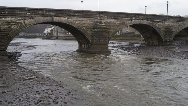
Every city that built itself on a river solved the same engineering problem: how to cross moving water repeatedly, cheaply, and permanently. The answer was always some version of a pier – a structure designed to sit in the current, resist it, and transfer its loads into the riverbed. Hundreds of thousands of those structures now exist in cities worldwide. None were designed to generate power. All of them are surrounded by it.

Classical hydroelectric generation requires a dam, a reservoir, and a height differential. Water falling creates work. The infrastructure requirement is enormous, site constraints are severe, and the ecological cost is high. Hydrokinetic power operates on a different principle entirely. It extracts energy from the horizontal motion of flowing water, with no change in elevation and no flow modification. The turbine sits in the current, the current turns it, the rotation drives a generator. The river is not blocked. It is borrowed from.
For cities built on rivers, the implication is direct. The infrastructure a hydrokinetic installation needs – stable structures standing in moving water, already designed to handle lateral hydraulic loads – exists in every urban river crossing already built. A retrofit device does not need to construct a foundation in a riverbed. It uses the one already there.
What the Retrofit Device Actually Is
A conventional hydroelectric plant is a facility. The hydrokinetic bridge retrofit described here is closer to a product – a modular assembly that ships to a site, attaches to existing structure, and begins generating power without excavation, without diversion works, and without modifying anything the installation did not bring with it.
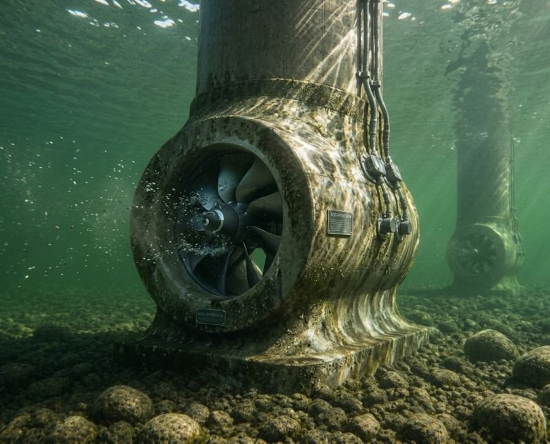
The physical form this concept describes is a sleeve: a structural ring or partial enclosure that wraps around a bridge pier below the waterline. Attached to the sleeve are one or more turbine rotors, sized to operate within the pier’s hydraulic shadow. The sleeve transfers all turbine loading back into the pier’s existing structure rather than into the riverbed. A sealed generator housing sits above the waterline or at the tidal interface zone. Electrical output routes through the bridge’s existing conduit infrastructure – most modern bridges carry cable runs for lighting, sensors, and communications – and connects to the urban distribution grid or a local microgrid.
The Sleeve, the Rotor, and the Flow Geometry
The key insight in the device’s layout is that a bridge pier already modifies the flow around it. Water approaching a cylindrical or rectangular pier accelerates around its edges before reuniting downstream. The physics behind this acceleration is covered in detail in the Fluid Dynamics in Hydro Power science article. For the retrofit device, this matters practically: a rotor positioned at the flow-acceleration zone of a pier encounters local current speeds 15 to 25 percent above the river’s mean velocity. On a river averaging 2.0 meters per second, that rotor sees 2.3 to 2.5 meters per second. Power output scales with the cube of velocity, which makes rotor placement geometry more valuable than rotor size.
Structural Integration Without Touching the Foundation
Bridge piers carry vertical deck loads and lateral hydraulic loads from current, wind, and sometimes ice. The retrofit sleeve introduces a new lateral load source – turbine thrust – that the original design did not account for. The device routes that thrust through the sleeve’s clamping mechanism and distributes it along the pier shaft rather than concentrating it at a single point.
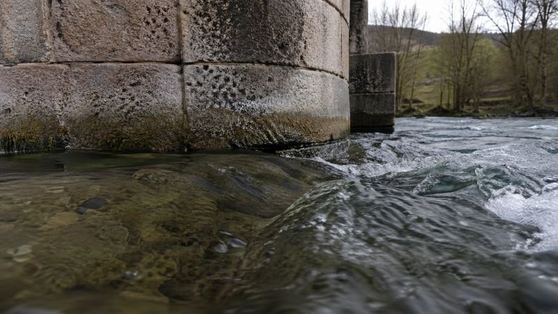
What the sleeve cannot do is attach to a pier whose structural condition is already marginal. A load-bearing assessment of the host structure is the first step of any installation – not because turbine thrust forces are large (typical values for a 10-kilowatt hydrokinetic unit run 2 to 5 kilonewtons), but because urban bridge inventory varies enormously in age and condition. A nineteenth-century masonry arch bridge and a 1980s reinforced concrete span are not the same engineering problem, and the sleeve design does not pretend otherwise.
How the Device Could Operate
The basic hydrokinetic power calculation uses the kinetic energy formula for fluid flow:
P = 0.5 x rho x A x v³ x Cp
Rho is water density (approximately 1,000 kg/m³ for freshwater). A is the rotor swept area in square meters. V is flow velocity in meters per second. Cp is the power coefficient – the fraction of available kinetic energy the turbine actually captures. The Betz limit sets the theoretical maximum at 59 percent; real deployments typically achieve 35 to 45 percent. For the retrofit concept, 40 percent is a reasonable working number.
Power from a Pier: The Arithmetic
For a rotor with a 1.0 meter diameter (swept area approximately 0.79 m²), operating at 2.0 m/s with a 0.40 power coefficient:
P = 0.5 x 1,000 x 0.79 x 8.0 x 0.40 = approximately 1,260 watts
At 2.5 m/s, exploiting the acceleration zone at the pier edge:
P = 0.5 x 1,000 x 0.79 x 15.6 x 0.40 = approximately 2,460 watts
Four rotors distributed around a single pier: 5 to 10 kilowatts continuous output. A bridge with four piers in the active channel: 20 to 40 kilowatts. A city with 15 viable bridges on a fast river corridor: 300 to 600 kilowatts of distributed baseload generation, running continuously, from infrastructure already standing in the river. That is not a power station. It is roughly the continuous electrical demand of 200 to 450 average European households.
The manufacturing energy question is worth asking here, even if only briefly. A pier-mounted sleeve turbine assembly at this scale involves roughly 400 to 800 kilograms of steel and composite materials. At an average embodied energy of 20 MJ/kg for mixed steel and polymer components, the manufacturing energy cost sits around 8,000 to 16,000 MJ per pier installation. At 5 kilowatts of continuous output, a single pier unit generates approximately 157,000 MJ per year. Manufacturing payback: 2 to 3 months. That number is different from a home staircase energy harvester by several orders of magnitude. The host infrastructure already exists, the current already flows, and the scale of extraction is high enough relative to installation cost to make the comparison meaningful.
Everything here is free. Readers are the reason it stays that way.
I make all of it alone, with no ads. If it is worth a coffee a month to you, that keeps the next one coming.
Keep it alive →Which Urban Water Structures Actually Work
Flow velocity decides everything, and the cube relationship in the power formula punishes slow rivers without mercy. A river at 1.0 m/s delivers one-eighth the kinetic energy of a river at 2.0 m/s. That asymmetry eliminates a large fraction of urban bridge inventory immediately.
| Infrastructure Type | Typical Flow Speed | Retrofit Suitability | Notes |
|---|---|---|---|
| Bridge pier on fast urban river | 1.8 – 3.5 m/s | High | Flow acceleration zones at pier edges increase local velocity 15-25% |
| Bridge pier on slow lowland river | 0.3 – 0.8 m/s | Poor | Below practical hydrokinetic threshold for useful output |
| Urban quay wall | 0.5 – 2.0 m/s | Moderate | Highly variable – local channel geometry determines whether it qualifies |
| Tidal estuary bridge | 1.5 – 3.0 m/s (bidirectional) | Very High | Predictable twice-daily reversal, no weather dependency on schedule |
| Urban drainage culvert | 1.0 – 4.0 m/s | Moderate to High | High velocities but small cross-sections constrain rotor diameter |
| Canal lock approach | 0.2 – 0.5 m/s | Very Poor | Managed slow flow, unsuitable regardless of channel depth |
Why Slow Rivers Do Not Improve With More Bridges
Cities built on wide, flat lowland rivers have a structural problem with this concept. Amsterdam’s canals run at 0.1 to 0.3 meters per second – hydrokinetically inert regardless of how many bridges cross them. Most rivers traversing central European plains fall into the same category. The device does not change that. The cube law does not negotiate.
London’s tidal Thames offers a useful contrast. Above the tidal limit, at Richmond, mean flow runs 0.5 to 1.2 m/s – marginal at best. Below the tidal limit, under bridges like Waterloo or Blackfriars, tidal exchange drives currents of 2.0 to 2.5 m/s during peak flow. The bridge piers standing in the tidal Thames are sitting in some of the most energetically consistent flow in any major European city, generated by gravitational mechanics rather than rainfall, and the fact that none of them currently generate electricity is one of the more interesting gaps in urban energy planning.
Quays, Culverts, and the Drainage Network
Quay walls and waterfront pier structures are geometrically similar candidates to bridge piers. A wall-mounted bracket supporting a cantilevered rotor assembly facing the channel current applies the same concept with minor adaptation. Urban drainage and combined sewer overflow channels present a different sub-case: velocities reaching 3 to 4 meters per second in channels that are already enclosed, already managed, and already accessible through maintenance infrastructure. The cross-sections are small, which limits rotor size, but the velocities are high enough that compact axial-flow units could extract meaningful output from infrastructure that currently has no energy function at all.
Tidal Estuaries as the High-Value Edge Case
A tidal river offers what a freshwater river cannot: certainty. Tidal current runs on an astronomical schedule – twice daily, reversing direction at known times, predictable years in advance with no reference to weather. A retrofit device on a tidal estuary bridge uses bidirectional rotors or reversible-pitch blades to generate power on both flood and ebb tides, operating on a six-hour rhythm that no storm can cancel. The science of how lunar gravity translates into hydraulic current is examined in the Tidal Energy: Predictable Power from the Moon article. For the retrofit concept, the relevant point is that port cities historically built their infrastructure at tidal river locations because the water was deep and fast. The bridges and the energy opportunity coincide by historical accident, not design.
What the River Brings That the Design Did Not Plan For
A device permanently submerged in an urban river is not operating in a controlled environment. It is in a system that periodically carries tree trunks, shopping trolleys, ice sheets, and sediment plumes. The retrofit concept has to address that without softening it.
River debris is the maintenance problem most likely to limit operational lifespan. Hydrokinetic rotors present a swept area to the current. Anything larger than the rotor gap arriving in the flow will catch, wrap, or strike. Debris management in this design works through two mechanisms: a coarse upstream screen on the sleeve to deflect large objects, and rotor blade geometry optimized for self-clearing – blades angled to shed flexible material rather than entangle it. Neither mechanism handles a major flood event carrying full tree sections. Those events require a shutdown protocol.
Aquatic ecology introduces a different constraint. Rotating blades in a fish-bearing river need careful design to minimize strike probability. The fish passage problem is well-documented in conventional hydropower engineering and the physics apply directly here. The critical design parameter is blade tip speed, not rotor diameter. Slow-rotating large-diameter rotors at urban river current speeds produce strike rates significantly lower than the visual impression of moving blades suggests, but the rotor geometry has to be designed around that constraint from the start, not adjusted after the turbine is already in production.
Navigation defines the spatial envelope. A bridge with turbines on its piers introduces submerged obstacles in channels that may be used by commercial or recreational vessels. The retrofit installation footprint must stay within the pier’s existing hydraulic shadow – the zone the bridge structure already excludes from navigation. Any extension beyond that shadow creates a new hazard, requires navigational marking, and triggers a separate approval process with waterway authorities. The device concept works inside the shadow. It does not claim more of the river than the bridge already occupies.
From One Pier to a River Corridor Grid
A single turbine on a single pier is a demonstration. What the concept becomes at scale is a different kind of infrastructure.

A city with a navigable river under 40 bridges has, in principle, 40 candidate sites distributed along a linear corridor through the city. If a third are structurally suitable and hydraulically viable, the river corridor becomes a distributed generation network with 13 to 15 active nodes. Each node is modest. The aggregate begins to look like a continuous baseload source – geographically dispersed, with no single point of failure, and no fuel input.
Grid integration for a distributed system like this follows the same logic as aggregated rooftop solar, with one significant difference: solar output is weather-dependent and diurnal. Hydrokinetic output from a river corridor is near-continuous. Hydraulic variation between bridge locations creates slight phase differences in generation that, at the grid level, smooth aggregate output rather than destabilize it. The river does not produce identical flow at every crossing. Channelization, bends, and tributary confluences create local variation that distributed generation can absorb.
The evolutionary arc for this concept runs from a single experimental installation, through multi-rotor deployment on one bridge, to corridor-level networked operation. Cities that begin with one unit are simultaneously testing structural integration, debris management, ecological impact, and regulatory compliance. All four are prerequisites for corridor-scale deployment. None can be shortcut, and the knowledge gained at single-pier scale does not transfer to corridor scale without deliberate documentation and redesign.
Developing cities with fast rivers and less complex waterway approval processes may move through this arc faster than cities in northern Europe or North America, where navigation authority approvals, environmental impact assessments, and heritage structure constraints add years to any waterway installation. The physics is the same everywhere. The institutional velocity is not. A city that decides to run this experiment seriously, in the right river geography, with a regulator willing to move, is probably closer to corridor-scale operation than most current estimates assume.
The View From NoSuchDevice
I find this concept genuinely interesting for a reason that is mostly geometric rather than idealistic. The infrastructure is already there. The water is already moving. The energy has been flowing past every bridge pier in every river city for as long as bridges have existed, and no one has asked the piers to do anything with it. That is a strange situation. It does not require new physics to fix.
The honest version of this idea is not a universal urban energy solution. Most cities do not have fast rivers, and the slow-river problem is not a design challenge to overcome – it is a physics limit. A river at 0.5 meters per second is not a viable hydrokinetic source regardless of how many bridges cross it, and no amount of engineering optimism changes the cube law. The concept is a specific solution for a specific subset of cities, and it would be dishonest to present it otherwise.
Where I think the case is genuinely strong is the tidal estuary scenario. A bridge over a tidal river in a major port city is already sitting on one of the most energetically consistent and predictable sources available in any urban environment. Twice daily, on an astronomical schedule, large volumes of water move through those channels in both directions. The bridge piers are already there. The current is already there. The manufacturing energy payback at pier-level output is a matter of months, not decades. The numbers point in the right direction on every dimension that matters.
The first seed form of this device – a few rotors on a few piers somewhere on a tidal river in a city willing to run the approval process – is probably 10 to 15 years from routine deployment. The mature form, a river corridor managed as a distributed generation asset alongside solar and wind in a city’s energy portfolio, is the destination worth engineering toward. Whether any city moves toward it in the next decade depends less on the physics than on whether someone decides to start the permit applications.
You read the whole thing.
That is rarer than it should be, and it is the exact kind of attention I built this archive for. I make every piece alone, with no ads and no investor deciding what gets written. If you want the next machine taken apart like this one, you can help me make it.
A coffee a month is enough to keep it free for everyone.
Prefer crypto or a one time gift? Other ways to give →