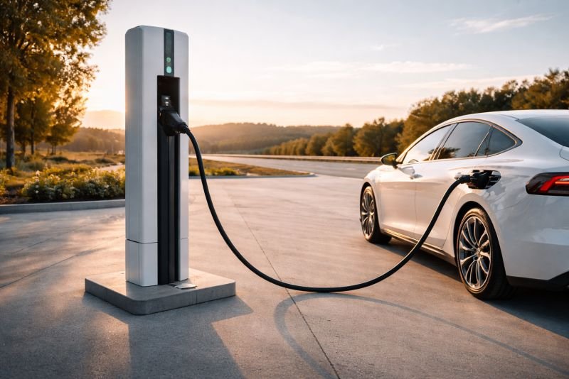
A driver pulls into a highway rest stop, connects a cable, and does not walk anywhere. Four minutes and forty seconds later, the cable disconnects. The car has 75 kilowatt-hours stored. The charging column is cool to the touch – not warm, cool – because the physics that makes this possible generates almost no heat in the process of delivering energy at a rate that would destroy any lithium battery on the market.
That particular detail, the temperature of the column, tells you more about how the device works than any specification sheet. Moving charge across a graphene electric double layer is not the same kind of event as pushing lithium ions through solid electrolyte. The thermal physics are different at the root.
The short version: A graphene supercapacitor charging unit stores energy in a bank of graphene electrodes and releases it to an electric vehicle at rates no lithium chemistry can sustain – 75 kWh in under five minutes. The active graphene surface inside the device covers roughly 3,500 square meters, folded into a column about the size of a large industrial cabinet. Speed comes from the physics of electric fields rather than ion migration. The constraint is manufacturing precision, not thermodynamics.
Key Takeaways
- Five-minute EV charging is not faster battery chemistry – it requires a different class of physics, and the graphene supercapacitor charging unit is built around exactly that difference
- The device carries its own energy buffer not as a workaround but as a design choice: accumulate slowly from the grid, discharge fast into the vehicle
- Graphene supercapacitors respond to cold weather differently from lithium – slower, not damaged – and that distinction matters more than it first appears
- A cluster of ten units at a highway facility holds over 700 kWh of instantly available storage, which is not just a vehicle service; it is distributed grid infrastructure operating under a different name
- The open question for this device has never been whether the physics works; it has always been whether graphene can be manufactured at the purity and uniformity the device requires
Table of Contents
Why Graphene Supercapacitors Run Cool Where Lithium Would Fail
Delivering 75 kWh in 45 minutes requires an average power of 100 kilowatts – already comparable to peak draw in a small office building. Delivering the same energy in five minutes requires 900 kilowatts, sustained. No lithium chemistry accepts charge at that rate without generating heat faster than any thermal management system removes it. The limitation is not investment or ambition. It is a physical consequence of forcing ions through solid electrolyte at high current, and incremental chemistry improvements raise the threshold modestly rather than moving it.
The Trade-Off Graphene Changes
Supercapacitors store energy in an electric field across two electrode surfaces separated by an electrolyte. The physics of electrochemical double-layer capacitance means charge accumulates at the electrode surface rather than migrating through it, which is why the process tolerates extreme rates with almost no thermal output. The trade-off is energy density. Standard activated carbon supercapacitors store 5 to 10 Wh/kg. Lithium batteries store 150 to 250. That gap used to make supercapacitor-based EV charging impractical regardless of speed.
Graphene changes the geometry of that trade-off. Capacitance scales directly with electrode surface area, and graphene in its ideal form offers 2,630 square meters of active surface per gram – the theoretical maximum for a single atomic layer. High-quality graphene electrodes in the device described here operate at 1,800 to 2,200 square meters per gram after accounting for layer stacking effects. That pushes energy density toward 40 to 60 Wh/kg. Still below lithium. No longer in a different universe.
The Number That Anchors Everything
At 50 Wh/kg, storing 75 kWh requires roughly 1,500 kilograms of electrode and electrolyte material. The full unit with housing, thermal regulation, and power electronics lands at 3 to 4 metric tons and occupies 2.5 to 3 cubic meters – a column about 2 meters wide, 2 meters deep, 2.5 meters tall. Heavy enough that nobody is moving it. Compact enough that a highway facility installs a row of them without redesigning the lot.
The weight is worth holding onto. At 50 Wh/kg, the device stores energy at roughly one-quarter the density of a lithium pack. It compensates by not going anywhere. Its job is to stay in one place and be ready.
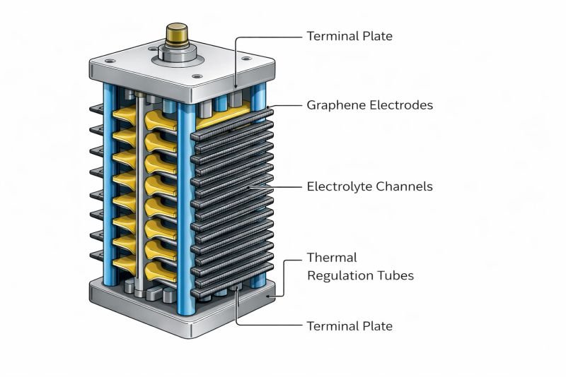
What Lives Inside a Graphene Supercapacitor EV Charger
The charging unit is not a power converter attached to a cable. It is closer to a pressurized reservoir. A sealed graphene electrode bank occupies the central volume. Electrolyte fills the space between electrode layers. Thermal regulation channels run through the structure in a grid pattern. Power electronics at the output stage handle conversion and delivery to whatever connector standard the vehicle uses.
The Hybrid Configuration
A secondary lithium module – around 20 kWh – sits alongside the main graphene bank. Its function is housekeeping, not delivery. Between vehicle arrivals, it trickle-charges from the grid and tops up the graphene bank. During cold weather conditioning, it provides thermal stability while the graphene bank warms to operating range. Every delivery to every vehicle comes from the graphene bank. The lithium module handles everything else.
The Buffer Architecture
The device draws from the grid continuously at a moderate, predictable rate – typically 50 to 100 kilowatts – and accumulates that energy in the graphene bank between arrivals. When a car connects, the bank discharges at 800 to 1,000 kilowatts into the vehicle. The grid never sees the delivery spike. Accumulating slowly and releasing fast is not a compromise built around external constraints; it is the architecture that makes fast delivery possible in the first place.
How a Graphene Supercapacitor EV Charger Works
The charging sequence begins before the car arrives. The graphene bank holds a charge state between 70 and 90 percent during standby. When a vehicle connects, the power electronics reads the car’s battery state – voltage, current tolerance, thermal status – and calculates a delivery profile. Then it opens the discharge path.
The Energy Arithmetic
The energy stored in a capacitor bank follows one equation:
E = ½ × C × V²
Where E is energy in joules, C is capacitance in farads, and V is voltage across the bank.
To store 75 kWh (270,000,000 joules) at an operating voltage of 1,000 volts:
C = 2E / V² = 2 × 270,000,000 / (1,000)² = 540 farads
540 farads at 1,000 volts. A finger-sized supercapacitor cell offers 3,000 farads at 2.7 volts. Scaling to 1,000 volts requires stacking cells in series – each step up in voltage reduces effective capacitance of the stack. Reaching 540 effective farads at operating voltage requires manufacturing uniformity across every cell in the stack. One outlier cell limits the entire series. That is where the precision problem lives: not in the graphene physics, but in cell-to-cell consistency across a stack of hundreds.
At 900 kilowatts sustained output, 75 kWh takes exactly five minutes. Delivery rate declines slightly as the bank discharges, so the practical window is 4:40 to 5:15 depending on vehicle state at arrival.
Thermal Behavior at Temperature Extremes
At -20 degrees Celsius, electrolyte viscosity rises and ion mobility slows. Effective capacitance drops 15 to 25 percent compared to room temperature. The device extends the delivery window and draws on the lithium buffer for the initial transfer phase while the main bank warms. At 40 degrees Celsius, the supercapacitor operates near its optimum – higher temperature improves ion transport across the double layer.
The comparison with lithium behavior matters here. A lithium battery charged aggressively at -20 degrees risks permanent damage through lithium plating. The graphene supercapacitor at -20 degrees is slower, not damaged. The cold failure mode is inconvenience. The heat failure mode – above 65 degrees inside the bank, sustained – is gradual electrolyte degradation over years, not an acute event.
Regenerative Braking as an Input Channel
Vehicles arriving at a highway rest stop brake from motorway speeds. A hard stop from 100 km/h in a 2,000 kg vehicle dissipates roughly 77 kilojoules of kinetic energy. The graphene bank accepts this pulse directly through a bidirectional port in the docking sequence without stress. Across hundreds of arrivals per day, the recovered energy per event is small – around 0.02 kWh – but the bank absorbs it without the thermal management overhead that would accompany the same pulse in a lithium system.
Everything here is free. Readers are the reason it stays that way.
I make all of it alone, with no ads. If it is worth a coffee a month to you, that keeps the next one coming.
Keep it alive →Why This Graphene Supercapacitor Charger Only Works at a Highway Stop
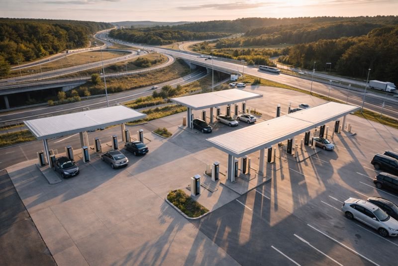
A device weighing 4 metric tons that needs 20 minutes to recharge between sessions is not a home appliance. Occasional use at low traffic volumes makes poor use of the buffer architecture – the energy arithmetic only works when the bank cycles repeatedly through the day. The graphene supercapacitor charging unit performs in one context: high-throughput locations where vehicles arrive in sequence and dwell time carries a real cost.
Highway rest stops process hundreds of vehicles per day. At five minutes per session and a 20-minute recharge interval between deliveries, a single unit serves 3 to 4 vehicles per hour continuously. A facility with 8 units serves 25 to 30 vehicles per hour – comparable in throughput to a conventional fuel station, with a fundamentally different energy architecture underneath.
| Parameter | DC Fast Charger (current form) | Graphene Supercapacitor Unit (mature form) |
|---|---|---|
| Charge time (75 kWh) | 20-45 minutes | 4-6 minutes |
| Peak output power | 150-350 kW | 800-1,000 kW |
| Grid draw per session | 75-100 kWh direct | Low – buffer refill only |
| Energy density (storage) | N/A – direct grid | 40-60 Wh/kg |
| Cold weather behavior | Degraded, damage risk | Degraded, no damage |
| Heat failure mode | Thermal runaway risk | Gradual electrolyte wear |
The grid draw row is where the device surprises. Because every delivery comes from the local buffer rather than the grid in real time, a busy station with 8 units looks to the grid like a single moderate commercial load. The high-power delivery events are invisible at the grid level. Whether that matters for grid planning depends on how energy systems evolve around this device – but the architecture produces this property without being designed for it.
How a Graphene Supercapacitor Charger Fails – and How It Recovers
Physical puncture of the sealed electrode chamber releases electrolyte. High-voltage supercapacitor electrolytes use organic solvents with varying degrees of flammability. A breach is not equivalent to a lithium battery thermal runaway – there is no cascading electrochemical chain reaction, just a contained solvent release requiring ventilation and standard fire suppression response. The device requires physical impact barriers on vehicle-accessible sides, which is standard installation practice at highway facilities.
Rapid full discharge into a short circuit – if the output protection electronics fail while the bank is fully charged – produces a very large current pulse over a very short duration. Internal bus bars are rated for this scenario. The protection logic in the power electronics handles it in normal operation. What it cannot handle is being the failure point itself, which is the open question in any active protection system.
Long-term electrolyte degradation is the slow failure mode. Above 65 degrees Celsius, sustained, electrolyte molecules break down and byproducts raise internal pressure. The sealed chamber has calibrated pressure relief valves. Over a decade of operation in hot climates with inadequate thermal management, effective capacitance falls 20 to 30 percent. The device does not stop suddenly. It becomes progressively less capable until a maintenance cycle identifies the trend.
When Graphene Supercapacitor Charging Stations Start Acting Like the Grid
A single unit holds 75 kWh. Ten units at one highway facility hold 750 kWh of fast-response distributed storage. A national highway network with 2,000 such facilities holds 1.5 gigawatt-hours of storage spread along the corridors where vehicle energy demand is highest.
At that scale, the device is no longer a charging service. When renewable generation overshoots demand at midday, the highway buffer absorbs the surplus. When evening demand peaks, the buffer contributes to local grid stability while handling arriving vehicles simultaneously. The highway rest stop becomes a node in a distributed energy layer that nobody designed for that purpose – it emerged from the logic of the device and the geography of roads.

The open questions at this system level are not physics questions. Every kilowatt-hour flows correctly according to known electrostatics. The open questions are institutional: who owns the buffer capacity of a highway charging facility, how does a road authority negotiate with a grid operator for energy storage services, what governance structure handles conflicts between vehicle charging demand and grid stabilization demand at the same moment. These are coordination problems, not physical ones. Physics settled its part before the institutions knew the conversation was starting.
The arc of this device class runs from proof-of-concept column to highway network to regional distributed buffer. At each stage, the graphene supercapacitor charging unit acquires a function it was not specifically built for, because the physics that makes it fast at one thing makes it useful for the others. That is what distinguishes a seed technology from a product: a product solves a defined problem; a seed keeps revealing new problems it can address without modification.
The View From NoSuchDevice
I find this device interesting for a reason that gets lost in the five-minute headline. Five minutes is what everyone leads with, and it is a real human benefit. The interesting number, to me, is what the device looks like to a grid operator.
A network of graphene supercapacitor charging stations draws slowly, stores locally, and releases fast. The grid sees a distributed array of slow predictable commercial loads. The high-power delivery events are invisible at the grid level. That is a quiet inversion: a device designed to serve vehicles faster than any grid can deliver turns out to make the grid’s management problem easier. I did not expect that when I first looked at the energy arithmetic, and I still find it worth thinking about.
What I am less settled on is the production path. The physics of a graphene electrode at 2,000 square meters per gram is not in question – it behaves exactly as predicted. Getting consistent, defect-minimal graphene at the quantities this deployment requires is a different kind of problem, one that lives in production chemistry rather than physics. A graphene electrode with a defect density above a certain threshold loses capacitance and uniformity. Solving that at manufacturing scale is the actual constraint. Not the device design. Not the energy arithmetic.
I think the highway deployment context is correct. It is the right location, the right use case, and the right throughput to make the cycle economics work. Trying to deploy devices this heavy into apartment building parking structures or suburban retail lots before the production chain matures would optimize for the wrong sequence. Start with high-throughput highway facilities, prove the cycle economics over five years, then decide what the next deployment class looks like.
The seed technology framing is not promotional. A national highway buffer network is structurally different from anything that currently exists in energy infrastructure. It is distributed fast-response storage that happens to interface with vehicles. Whether the institutions that eventually build it understand what they are actually building will determine how well they design the governance layer around it. The physics does not care either way.
You read the whole thing.
That is rarer than it should be, and it is the exact kind of attention I built this archive for. I make every piece alone, with no ads and no investor deciding what gets written. If you want the next machine taken apart like this one, you can help me make it.
A coffee a month is enough to keep it free for everyone.
Prefer crypto or a one time gift? Other ways to give →