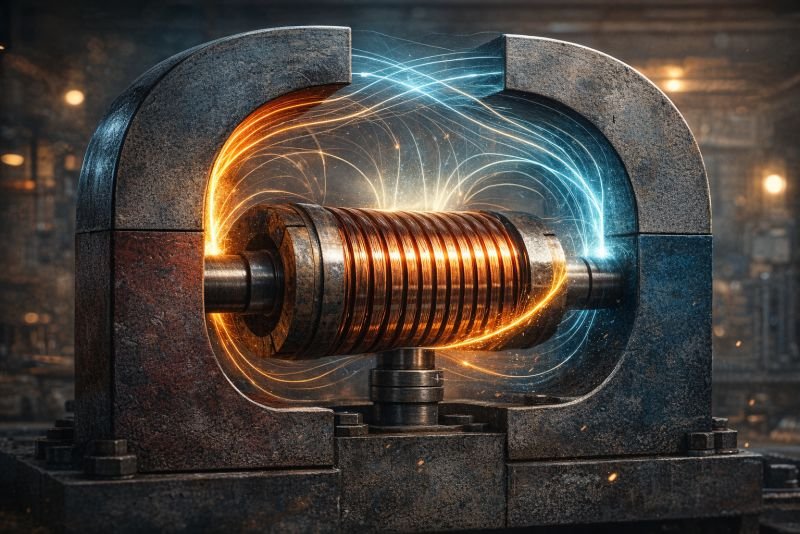
In 1831, a man in London wound two coils of wire around opposite sides of an iron ring and connected one coil to a battery and the other to a galvanometer. When he switched the battery circuit on, the needle of the galvanometer twitched. When he switched it off, the needle twitched again, in the opposite direction. In between, with the battery running steadily, nothing happened at all.
That man was Michael Faraday, and what he had just noticed was not an accident. The galvanometer only moved when something was changing. The magnetic field had to be moving, growing, or collapsing for any current to appear. A steady magnet, no matter how powerful, produces nothing.
Change is the requirement.
The short version: Electromagnetic induction is the production of electric current in a conductor by a changing magnetic field. Every generator in every power station on Earth works by spinning a coil of wire inside a magnetic field, exploiting this effect continuously. The relationship between the rate of change and the voltage produced is described by Faraday’s law, which puts a precise number on exactly how much current any given motion will generate. A coil rotating at 50 cycles per second in a magnetic field of 1 tesla across an area of 0.1 square metres will produce a peak voltage of roughly 31 volts per turn of wire.
Table of Contents
What Electromagnetic Induction Actually Does to a Wire
The mechanism is worth examining closely, because the intuitive picture most people carry is slightly wrong in a useful way.
When a magnetic field changes near a conductor, it exerts a force on the electrons inside that conductor. The electrons, being charged particles in a changing field, experience a push. They move. Moving electrons are electric current. The wire did not need to be connected to anything, did not need a battery, did not need a chemical reaction. The changing field did the work.
What counts as “changing”? Three things produce the effect: a magnet moving toward or away from a stationary coil, a coil moving toward or away from a stationary magnet, or the magnetic field itself changing in strength while everything stays physically still. All three produce identical results. The physics does not distinguish between them. Only the engineering does.
The direction of the induced current follows a rule that annoyed nineteenth-century engineers and still catches people out today. The induced current always flows in the direction that would create a magnetic field opposing the change that caused it. Push a magnet into a coil and the coil generates a field that pushes back. Pull it out and the coil generates a field that tries to pull it back in. The coil is always braking the motion. This is not a flaw. It is the mechanism by which the moving magnet loses energy, and that lost energy becomes the electricity.
Faraday’s Law: The Equation That Built the Modern World
Faraday described what he observed, but it was James Clerk Maxwell who gave it a formula precise enough to engineer with. The relationship Faraday discovered is captured in this expression:
EMF = -N x (dPhi/dt)
Where EMF is the electromotive force in volts, N is the number of turns in the coil, dPhi/dt is the rate at which the magnetic flux through the coil is changing over time, and the negative sign captures the opposing direction of the induced current.
Magnetic flux, Phi, is the product of the magnetic field strength B and the area A of the coil perpendicular to the field. When a coil rotates in a uniform magnetic field, the flux through it changes continuously as the angle between the coil and the field lines shifts.
To see what the numbers mean in practice: take a generator coil with 500 turns of wire, rotating in a magnetic field of 1 tesla, with a coil area of 0.05 square metres. As the coil rotates at 50 cycles per second (the standard grid frequency in most of the world), the rate of flux change at peak reaches approximately 15,700 volt-turns per second. Divide that by 500 turns to get the contribution per turn, and multiply back through and the result is a peak EMF of around 15,700 volts total across the coil. Real generators then use transformer ratios to bring that to grid voltage. The number of turns is not decoration. Each one adds to the total.
The key insight from the formula is that voltage depends on rate of change, not on flux itself. A coil sitting stationary inside the strongest magnet on Earth produces zero volts. The same coil rotating slowly in a weaker field produces something measurable. Motion is not optional. It is the entire point.
The Variables That Control How Much Voltage Appears
Four physical quantities determine the output of any generator built on electromagnetic induction. Changing any one of them changes the output. Engineers use all four.
The first is field strength. Stronger magnets produce more flux through the coil, which means more flux change per unit of rotation, which means more voltage. Modern generators use powerful electromagnets rather than permanent magnets precisely because the field strength can be controlled. Varying the current through the electromagnet varies the output voltage without changing anything mechanical.
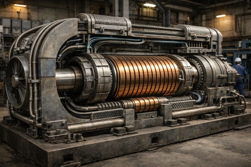
The second is coil area. A larger coil intercepts more magnetic flux. Doubling the area doubles the flux, doubles the rate of change, and doubles the output voltage. Large generators have large rotors. This is not arbitrary.
The third is the number of turns. Each loop of wire in the coil adds to the total EMF in series. Ten turns produce ten times the voltage of a single loop in the same field. Practical generators contain thousands of turns wound carefully to maximise the effect without adding excessive resistance.
The fourth is rotation speed. Faster rotation means the flux changes faster, which means higher voltage. Grid frequency is set by rotation speed. A 50 Hz grid runs its generators at exactly 50 revolutions per second (or a multiple thereof with the appropriate pole count). Let the speed drop and the grid frequency drops with it. Power stations spend considerable engineering effort keeping this number constant.
| Variable | Effect on EMF | Engineering Control Method |
|---|---|---|
| Magnetic field strength (B) | Proportional | Adjusting electromagnet current |
| Coil area (A) | Proportional | Physical rotor dimensions |
| Number of turns (N) | Proportional | Winding design |
| Rotation speed (dPhi/dt) | Proportional | Turbine speed regulation |
All four multiply together. A generator optimised on every variable simultaneously is what sits inside every large power station on Earth.
The Physical Limits Faraday’s Law Cannot Escape
Every technology built on electromagnetic induction operates inside hard boundaries. The physics allows enormous flexibility within those boundaries, but the boundaries themselves do not move.
The first limit is resistance. Every real conductor resists current flow, and resistance converts electrical energy into heat. A generator coil with high resistance loses a significant fraction of its induced EMF before the current leaves the machine. This is why generators use thick copper conductors wound with precision: thick wire has lower resistance, and lower resistance means more of the induced EMF becomes useful current.
The second limit is saturation. Magnetic materials can only carry so much flux. Push a generator’s electromagnets too hard and the iron core stops responding proportionally. Further increases in magnet current produce diminishing returns in field strength. Every real generator operates near but below this saturation point, which sets a practical ceiling on field strength and therefore on voltage per unit of physical size.
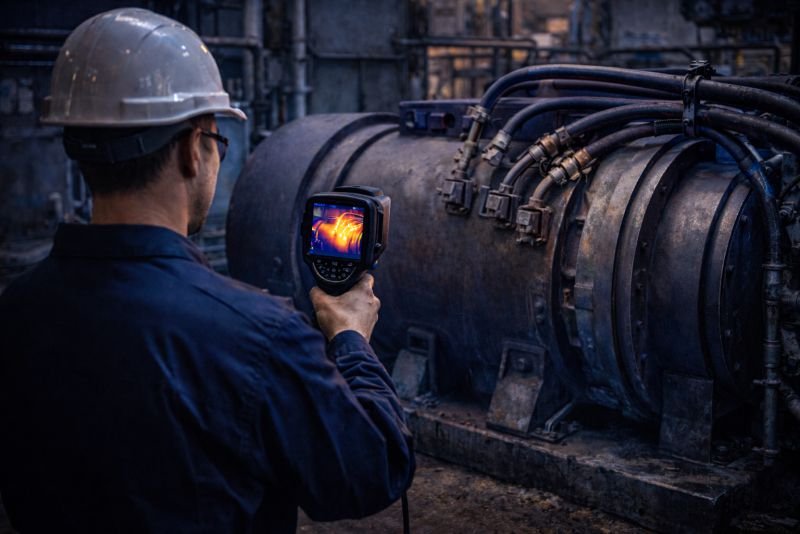
The third limit is heat. The combination of resistive losses in the coils and core losses in the magnetic material generates heat continuously during operation. Large generators require active cooling systems. The cooling requirement grows faster than the output as the machine is scaled up, which is part of why there is a practical maximum size for generators beyond which the engineering stops making sense.
The fourth limit is the speed of electromagnetic response. At extremely high frequencies, the induced currents in the conducting materials themselves begin to oppose the changing field in ways that reduce efficiency. This effect, called the skin effect, forces high-frequency machines to use stranded or thin conductors to remain effective. At grid frequencies of 50 or 60 Hz this is manageable. At higher frequencies it becomes a dominant design constraint.
Everything here is free. Readers are the reason it stays that way.
I make all of it alone, with no ads. If it is worth a coffee a month to you, that keeps the next one coming.
Keep it alive →How Engineers Turn the Principle Into a Machine
There is a gap between understanding Faraday’s law and building a working generator. The gap is mostly filled with decisions about geometry.
The basic problem is this: a coil rotating in a uniform magnetic field produces a voltage that rises and falls sinusoidally. At the moment the coil is parallel to the field lines, the rate of flux change is maximum and the voltage peaks. At the moment the coil is perpendicular to the field lines, flux change stops momentarily and the voltage reaches zero. This produces alternating current naturally, which is exactly what the grid needs.
Extracting that alternating current from a rotating coil requires a connection that rotates with it. The engineering solution is slip rings: circular metal contacts that maintain electrical connection while the coil turns freely. The current exits the spinning coil through brushes pressed against these rings, feeding into the stationary external circuit.
Direct current generators use a different solution called a commutator, which reverses the connection at precisely the moment the voltage would naturally reverse, so the output always flows in the same direction. The mechanical timing of this reversal is the entire trick of the DC generator, and it is considerably more difficult to maintain reliably than slip rings.
Modern large generators typically reverse the arrangement entirely. The magnets rotate and the coils stay still. The coil output does not need rotating contacts at all because the coils never move. This arrangement, used in virtually all utility-scale generators, removes the most mechanically vulnerable component from the machine and dramatically improves reliability.
Open Questions in Electromagnetic Induction Research
The principle itself is settled physics. What remains open is how far engineering can push it.
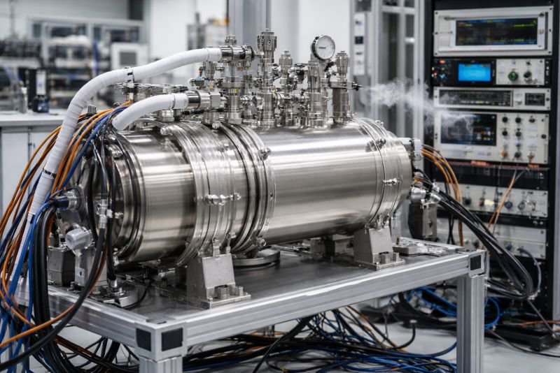
Superconducting generators represent the most active current research direction. A superconducting coil has zero resistance, which means none of the induced EMF is lost to heat in the windings. Generators built with superconducting coils can be dramatically smaller and lighter than conventional machines for the same power output, because the limiting factor is no longer resistive heating but pure magnetic flux capacity. The engineering obstacle is that superconductivity currently requires cooling to near absolute zero, which adds complexity and cost that offsets much of the benefit. Achieving superconductivity at higher temperatures would change that calculation entirely.
Amorphous metal cores are a more incremental development already entering commercial generators. Conventional electrical steel cores lose energy to internal magnetic reversals with every cycle. Amorphous metals, whose atoms are arranged randomly rather than in a crystal lattice, handle magnetic reversal with significantly lower losses. The improvement is measurable but not transformative. It is the kind of gain that matters at scale, across millions of generator-hours, rather than in any single machine.
High-temperature superconductors remain the research frontier where the most disruptive changes to generator engineering might eventually emerge. If the temperature threshold rises far enough, the cooling requirement disappears and superconducting generators become straightforwardly practical. How far that threshold can be raised remains an open question in materials physics.
Technologies That Exist Because of Electromagnetic Induction
Electromagnetic induction is not one application. It is the mechanism underneath most of what the electrical grid does.
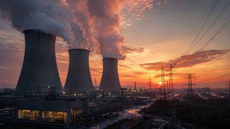
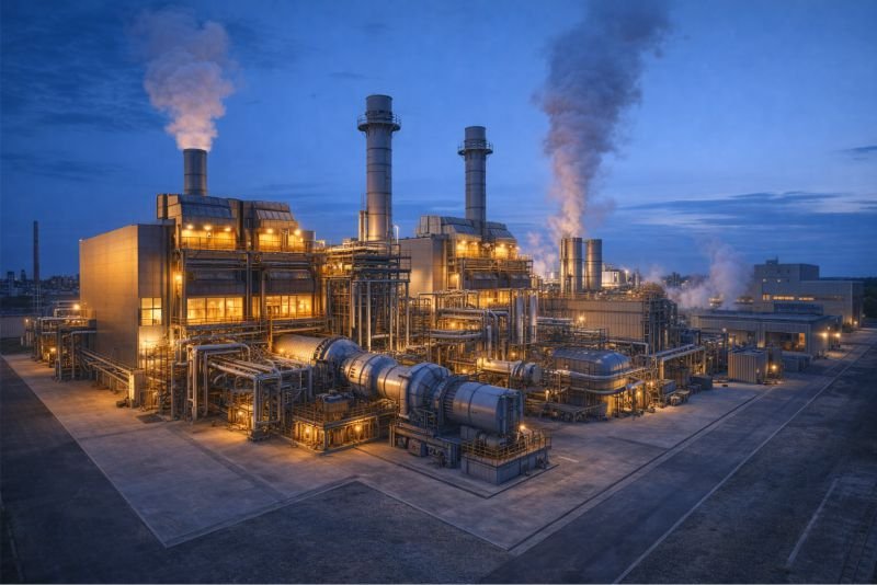
Every steam turbine power station, every gas turbine, every nuclear reactor’s electricity output depends on a shaft spinning a rotor past stator coils. The energy source varies. The conversion mechanism does not. Coal burns to boil water, water drives a turbine, the turbine spins a generator. The entire chain from fuel to grid current terminates in a rotating coil in a magnetic field.
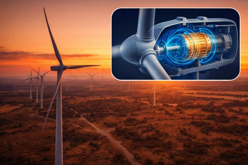
Wind turbines use the same principle with the wind providing the rotation. The engineering challenge in wind generation is that wind speed varies, which means rotation speed varies, which means frequency varies. Modern wind turbines solve this with power electronics that decouple the generator’s electrical output from the grid, allowing variable-speed operation while delivering fixed-frequency current. The induction principle is unchanged. The electronics between generator and grid absorb the speed variation.
Transformers use electromagnetic induction without any moving parts at all. A changing current in one coil produces a changing magnetic field, which induces a current in an adjacent coil. No mechanical connection, no rotation, no physical contact. The energy transfer happens entirely through the field. Every time electricity moves from a power station to a city at high voltage and then steps down to household voltage, it passes through a transformer exploiting this effect.
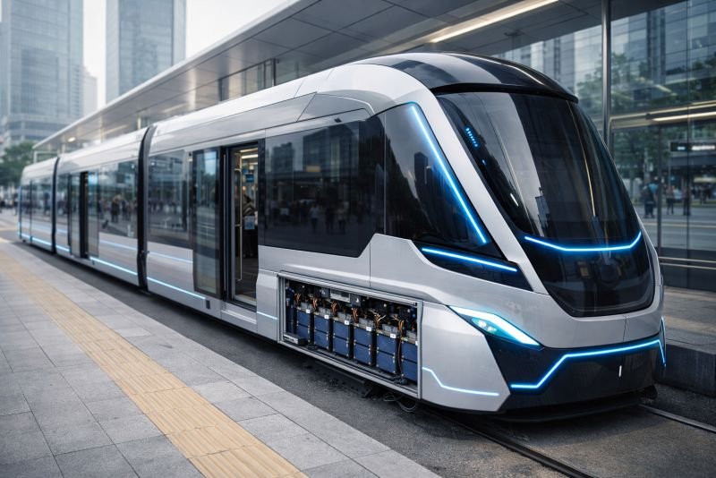
Electric motors run the same physics in reverse. Feed current through a coil in a magnetic field and the force on the conductor produces rotation. The generator converts motion to electricity. The motor converts electricity to motion. Both are the same physical law, read in opposite directions.
You read the whole thing.
That is rarer than it should be, and it is the exact kind of attention I built this archive for. I make every piece alone, with no ads and no investor deciding what gets written. If you want the next machine taken apart like this one, you can help me make it.
A coffee a month is enough to keep it free for everyone.
Prefer crypto or a one time gift? Other ways to give →
Technologies Related to This Concept
| Technology | Concept |
|---|---|
| Kinetic Energy Backpacks for Travelers | Concept: Backpacks equipped with generators that convert motion into power for charging devices. |
| Hydrogen-Powered Wireless Chargers | Concept: Wireless charging pads powered by hydrogen fuel cells. |
| Biomass-Fueled District Heating Systems | Concept: Communities using organic waste to power heating systems. |
| Micro Hydrokinetic Generators for City Rivers | Concept: Small-scale generators that harness energy from low-flow urban waterways. |
| Magnetic Monopole Energy Generators | Concept: Theoretical devices that exploit magnetic monopoles for unprecedented energy conversion. |