
In November 1940, the Tacoma Narrows Bridge shook itself apart in a 42 mph wind that would not have troubled a structure half its size. The failure had nothing to do with wind force. As airflow separated around the bridge deck, it shed alternating pressure pulses – one side, then the other – at a frequency that matched the bridge’s own resonance. Each oscillation amplified the next. Within hours the roadway was tearing itself free in 600-foot sections.
Structural engineers spent the following decades designing buildings, towers, and long-span bridges specifically to prevent this behavior. A micro vortex generator is a device that deliberately induces it – at a small scale, on a building facade, converting the same oscillation to electrical current instead of structural collapse.
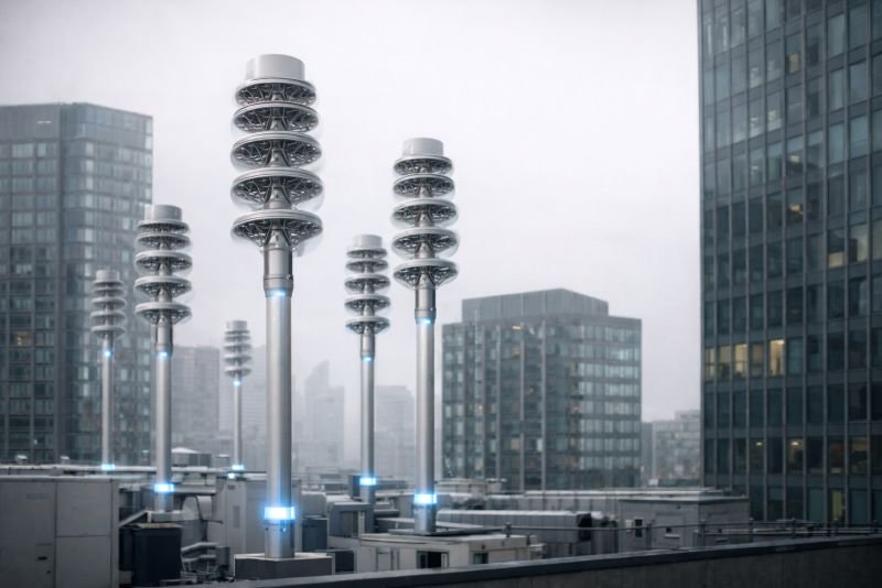
The short version: A micro vortex generator harvests energy from vortex-induced vibration in urban airflow. Wind moving past a slender body sheds alternating vortices that drive the body into resonance. A piezoelectric or electromagnetic transducer converts that oscillation to electricity. A single unit produces milliwatts. An array of 800 devices distributed across a building’s corner and edge geometry produces roughly 40 Wh per day – enough to run the building’s environmental sensor network and emergency lighting without grid connection, from energy the building was already shedding as turbulence.
Key Takeaways
- Urban turbulence intensity of 30-40% degrades conventional wind turbines to half their rated output – and is exactly the operating environment a vortex generator is tuned for
- The Strouhal number lets engineers calculate the device’s resonant frequency from geometry alone, before a single prototype exists
- At 30 Hz continuous operation, current piezoelectric ceramics begin measurable degradation within one to ten years – which is the real engineering problem this device has not yet solved
- A facade array that is not acoustically modeled can become audible through the building’s glass curtain wall – the noise question is structural, not cosmetic
- The long horizon here is not a better sensor charger: it is building facades designed from the start to generate power from their own aerodynamic geometry
Table of Contents
Why Urban Wind Damages Turbines but Feeds a Vortex Generator
A wind turbine installed on a rooftop in a dense city typically delivers 30 to 60 percent of its design rating in the field. This is well understood before installation. Developers install anyway, because acknowledging that the site is aerodynamically wrong for the device conflicts with planning approvals already obtained and subsidies already counted. Three years of measured output usually settles the argument in private.
What Turbulence Intensity Does to a Rotor
Outside a city, wind arrives with enough consistency for a horizontal-axis turbine to work with. Turbulence intensity – the ratio of wind speed fluctuations to mean wind speed – sits below 15 percent at rural and coastal sites. The rotor aligns with the flow, maintains rotational momentum between gusts, and operates near its design efficiency. Blade pitch is optimized for airflow that, while not perfectly steady, varies within a manageable range.
Inside a dense urban grid, turbulence intensity routinely exceeds 30 to 40 percent. Every parapet, every gap between structures, every facade corner fragments incoming air into eddies that shift direction over distances of a few meters. For a rotor, this means each blade passes through a continuously changing angle of attack on every revolution. Aerodynamic efficiency drops sharply. Fatigue loading on blade roots and hub connections increases. The relationship between urban turbulence and wind energy conversion is covered in full in the aerodynamics of wind turbines and kinetic energy; the relevant conclusion is that the rotor is not riding the wind. It is fighting it on every cycle, and the fight shows up in the output figures.
Vertical-axis designs tolerate multi-directional flow somewhat better, but they still depend on rotational momentum that intermittent gusts cannot sustain. Bearings and seals degrade faster in urban particulate loading than open-site specifications predict.
What That Same Turbulence Contains
Urban turbulence is not an absence of wind energy. It is wind energy in a form rotating machinery cannot process. The gusts, pressure pulses, and shed vortices that make a rooftop turbine miserable contain real mechanical energy – they just arrive without the directional coherence a rotor needs. A device that converts vortex motion directly, without asking the air to behave in ways cities structurally prevent, sees those same conditions as its operating environment, not its obstacle.
The city has been generating the input signal all along. The gap was the transducer.
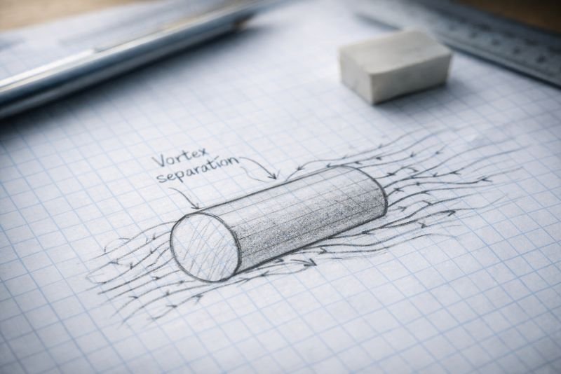
The Strouhal Number and the Geometry of Resonance
Telephone wires sing in wind. Most people have noticed and never investigated why a fixed wire produces sound – but the sound is the mechanism. As air flows past the wire, it separates at the surface and sheds alternating vortices, one side then the other, at a frequency determined by the wire’s diameter and the wind speed. The wire vibrates at that frequency and the vibration radiates as sound. Scale the same phenomenon up to a bridge deck and it can tear the structure apart. Scale it down to a 25 mm cylinder on a building facade and it becomes the energy input.
Tuning the Device to the Wind Before It Exists
The Strouhal number (St) connects vortex shedding frequency to body geometry and flow velocity:
St = f x D / V
Where:
- f = vortex shedding frequency (Hz)
- D = characteristic body dimension (m) – diameter for a cylinder, width for a beam
- V = flow velocity (m/s)
For a cylinder across a wide range of Reynolds numbers, St holds near 0.2. That consistency is what makes the relationship useful for design. If the dominant wind velocity in a specific urban corridor is known from measurement, the body geometry needed to produce resonance at that wind speed can be calculated before any hardware is machined.
A typical urban wind corridor sees a mean velocity of 4 m/s. A cylindrical body 25 mm in diameter sheds vortices at:
f = St x V / D = 0.2 x 4 / 0.025 = 32 Hz
Design the device to resonate mechanically at 32 Hz and it oscillates at maximum amplitude whenever the wind produces that shedding frequency. Different sites have different mean velocities and need different geometries. A corridor averaging 6 m/s needs a wider body, or the same body at a different orientation, to hold the same resonant frequency. The Strouhal number turns a wind measurement into a device specification – and it does so before a prototype exists.
Two Paths from Oscillation to Current
Once the body is vibrating, the oscillation needs to become electricity. Two transduction mechanisms are viable and they perform differently enough that the choice shapes where the device belongs.
Piezoelectric transduction bonds a piezoelectric element to the vibrating structure. Mechanical deformation generates charge – the same physical principle that operates gas lighters, ultrasound probes, and pressure sensors. The piezoelectric effect and mechanical energy conversion explains the underlying physics in full. For a vortex generator, the advantage is compactness: the transducer is embedded inside the device body with no external mechanism. The disadvantage is power density. Piezoelectric elements generate high voltage at low current, and extracting useful power from them at 30 Hz requires careful impedance matching in the conditioning circuit.
Electromagnetic transduction attaches a small magnet to the oscillating body inside a wound coil. Alternating current is generated directly. Output scales better with oscillation amplitude, which makes it more effective for larger bodies at higher wind speeds. The assembly is bulkier, but the technology for small electromagnetic generators is mature and well-characterized from microgeneration applications.
| Parameter | Piezoelectric | Electromagnetic |
|---|---|---|
| Power output per unit | Low (mW range) | Medium (mW to low W) |
| Voltage output | High, low current | Lower, higher current |
| Physical size | Very compact | Requires magnet and coil volume |
| Best wind speed range | Low to moderate | Moderate to high |
| Mechanical complexity | Minimal | Low |
| Preferred deployment | Dense facade arrays | Corridor-edge installations |
A sensor network drawing microwatts favors piezoelectric simplicity. A facade array feeding a building management system favors electromagnetic output. The site wind profile and the load profile together make the choice – and the transducer choice also determines which of the device’s two hardest engineering problems matters more.
How a Micro Vortex Generator Actually Operates
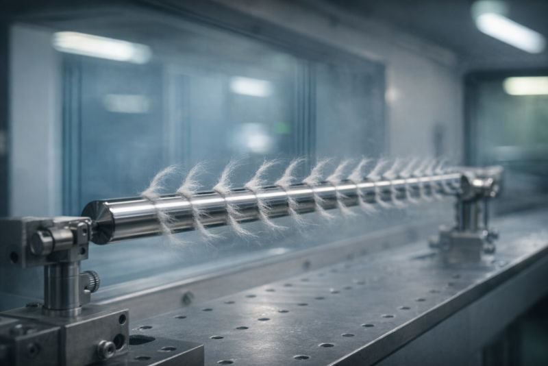
The device body is slender – a cylinder or tapered blade, typically 20 to 50 mm in characteristic diameter and 200 to 400 mm long, mounted as a cantilever from a fixed base or suspended between two support points on a flexible beam. At rest it is unremarkable. In a 4 m/s wind it oscillates visibly, sweeping a path of a few millimeters at its free end, 32 times per second.
From Airflow to Oscillation
Wind arriving at the body separates at the surface rather than flowing smoothly past. On one side, a vortex forms and grows until it detaches – and as it does, the pressure differential across the body gives the structure a small lateral push. A vortex then forms on the opposite side, detaches, and pushes back. The alternation is not random. At the frequency determined by the Strouhal relationship, it is periodic enough to drive the body into resonance, and resonance is where the amplitude grows from imperceptible to useful.
The mechanical response is nonlinear near resonance: a small increase in wind speed around the design velocity produces a disproportionately large increase in oscillation amplitude, and therefore in energy output. At wind speeds significantly above or below the design point, the shedding frequency drifts away from the body’s natural frequency and amplitude falls off sharply. The device is not a broadband harvester. It is a tuned resonator, and it performs best in the narrow band around its design condition.
From Oscillation to Power
In the piezoelectric configuration, one or more ceramic elements are bonded to the flexing section of the cantilever beam – the region of highest strain during oscillation. Each deflection cycle compresses and releases the ceramic, generating an alternating charge that a conditioning circuit rectifies to DC, accumulates in a small capacitor or thin-film battery, and delivers to the load when the accumulated energy crosses a threshold. The output is not continuous in the way a generator output is continuous. It is pulsed at the oscillation frequency and smoothed downstream.
In the electromagnetic configuration, a permanent magnet is fixed to the oscillating end of the device body and moves through a wound coil mounted on the fixed support structure. Each oscillation cycle induces an alternating current in the coil directly. The output frequency matches the oscillation frequency – 32 Hz in the design example – and a bridge rectifier and filter capacitor convert it to usable DC. Because the coil generates current proportional to the rate of change of magnetic flux, faster oscillation at higher wind speeds produces higher output without requiring additional circuitry.
In both cases the power conditioning electronics are small enough to sit in the device base. An array of devices connects to a shared bus at low voltage, and a single converter at the array level steps the aggregated output to whatever the downstream load requires. The individual device produces milliwatts. The bus delivers watts. The building management system sees a power source, not a physics experiment.
Everything here is free. Readers are the reason it stays that way.
I make all of it alone, with no ads. If it is worth a coffee a month to you, that keeps the next one coming.
Keep it alive →Where on a Building the Shedding Is Reliable
Not every surface on a building produces useful vortex shedding. A flat wall in parallel flow generates little periodic motion. A corner in crosswind generates consistent, predictable shedding that follows the Strouhal relationship closely. The device does not go where the wind is strongest. It goes where the building geometry turns that wind into a reliable oscillation.
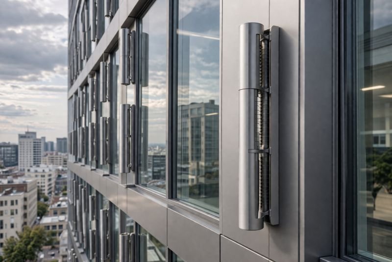
Facade Corners, Edge Geometry, and What 800 Devices Produce
The corners of a rectangular building shed vortices reliably when wind arrives within roughly 20 degrees of the building axis. Parapet edges, window reveals, and setback geometry on the facade face generate similar behavior at smaller scale. On a medium-size urban office building, the combined linear extent of corner and edge geometry across all four facades reaches roughly 80 meters.

At 10 cm spacing, 80 meters of edge supports 800 device positions. At a conservative average output of 5 mW per device across a 10-hour operating day:
800 x 0.005 W x 10 h = 40 Wh per day
Forty watt-hours per day will not offset a building’s heating load or displace a meaningful share of its lighting demand. It will run a dense wireless environmental sensor network continuously. It will power emergency lighting for 90 minutes. It will keep a building management system’s local processing nodes alive without grid connection. At 7 m/s – the kind of wind urban corridors see during storm conditions – output per device scales with velocity cubed, and the same array produces four to five times the calm-weather figure. The peak output arrives exactly when grid demand is highest.
The device is not competing with the grid on bulk generation. It is eliminating the grid connection requirement for low-voltage subsystems that currently need one – and it runs on turbulence the building produces regardless of whether any device is there to catch it.
Street-Level Corridors, Gap Flows, and the Acoustic Consequence
A gap between two buildings aligned with the prevailing wind accelerates flow through the Venturi effect, sustaining velocities 1.5 to 2 times the ambient wind speed at street level. Devices on the flanking walls of these corridors see above-average input with a consistency that rooftop locations rarely provide.
The acoustic problem is harder at street level. A device vibrating at 30 to 50 Hz produces sound near the lower boundary of human hearing. A single device at low amplitude is negligible. An array is not. When hundreds of devices shed vortices simultaneously, adjacent wake fields interact – either canceling or reinforcing, depending on spacing. A poorly designed array on a glass curtain wall can transmit audible vibration through the facade into occupied floors. At street level, that interaction is also a public environment problem.
Acoustic modeling of array geometry is part of the design, not an optimization step added afterward. Spacing, orientation offsets between adjacent devices, and frequency distribution across the array are parameters that need to be calculated before installation. No array has been built at the scale where this becomes the binding constraint, which means the answers currently exist in simulation, not in measured hardware behavior.
The Engineering Challenges That Are Not Optional
The physics of vortex-induced vibration is not in dispute. The Strouhal relationship has been measured and confirmed across a century of fluid dynamics research. The transduction mechanisms work in laboratory conditions. The reason a facade-scale array does not exist today is not unclear science – it is the gap between a laboratory demonstration and 25-year outdoor infrastructure, and that gap is wider than most published timelines on this technology acknowledge.

Materials Under Cyclic Loading in Urban Air
Lead zirconate titanate (PZT) is the piezoelectric material with the highest electromechanical coupling coefficient currently available. At 30 Hz continuous operation, a PZT element accumulates 10^9 stress cycles in roughly 385 days. Published fatigue data for PZT places measurable output degradation onset at 10^8 to 10^9 cycles. A device that needs to harvest energy for 20 years begins losing output in year one or two of continuous operation. That is not a manageable degradation curve – it is a product lifetime problem.
Polymer piezoelectrics – polyvinylidene fluoride (PVDF) and its copolymers – tolerate cyclic loading far better and survive urban temperature cycling between -15°C and +45°C without cracking. Their coupling coefficient is substantially lower than PZT, which reduces output per unit. The material research question is whether a composite can be engineered to combine PZT efficiency with PVDF mechanical tolerance. Work toward that answer has been advancing in materials science laboratories for two decades and has produced promising results in controlled conditions, but no composite has yet been deployed in outdoor infrastructure at scale.
Electromagnetic transducers are less vulnerable to fatigue, but the magnet-coil gap is sensitive to the particulate loading that urban air carries continuously. Sealing the mechanism against moisture and particles adds mass to the device body and changes its aerodynamic profile – which shifts the shedding frequency away from the Strouhal target. A sealed body is not the same aerodynamic object as the open design the calculation was based on. The correction is tractable, but it adds iteration cycles to the design process and makes field-tuning harder.
Maintenance on Surfaces Not Designed to Receive It
A sensor at facade height gets replaced on a predictable schedule when it fails. An array of 800 small devices distributed across all four faces of a building is a different maintenance proposition. Individual devices fail at different rates. One failed device in an array changes the local shedding pattern for its neighbors and may shift the array’s collective resonance characteristics. Monitoring which devices in an 800-unit installation have degraded requires embedded sensing, which requires power and data connections that add cost and installation complexity from the start.
Access to upper facade geometry requires rope access teams or building maintenance units. An intervention that takes 30 minutes at ground level takes four hours at height with associated safety and insurance requirements. Replacement cycles that look economically viable at prototype scale become significant operational costs at facade scale, and those costs need to be accounted for honestly before any deployment figure can be trusted.
Open Questions for Future Developers
The Strouhal calculation works cleanly when flow velocity and direction are predictable. Urban airflow is neither. Wind direction at a specific facade location shifts throughout the day and varies with approaching weather systems. A device tuned to 32 Hz at 4 m/s from the southwest performs differently when 6 m/s arrives from the northwest and the effective angle to the device geometry changes by 40 degrees.
Variable-geometry bodies that adjust their characteristic dimension to track a shifting shedding frequency are the theoretical solution. A body that can shift its effective diameter by 25 to 30 percent would maintain resonance across a useful operating range. Whether that is achievable without introducing the mechanical complexity that undermines the durability case is genuinely open. Passive approaches may be more practical: device bodies with two or three distinct resonant modes, or arrays distributed across a frequency band collectively, cover a wider operating range without moving parts.
The urban heat island effect introduces a second design variable that standard wind assessments miss. Cities run 2 to 6 degrees Celsius warmer than surrounding terrain, which lowers air density and modifies convective flow structure in the lower urban boundary layer. Lower air density reduces kinetic energy available at a given wind speed – typically 1 to 2 percent at realistic urban temperature differentials, small but not negligible in an energy budget already measured in milliwatts. More significant is the persistent low-level airflow that urban convection generates independently of synoptic wind conditions. A south-facing facade in a heat-island environment sees thermally driven upwelling during calm synoptic conditions that a standard wind resource assessment records as zero wind. Whether this convective input is consistent enough to be designed for has not been answered with field measurements at the relevant scale.
The optimal geometry for the device body – whether a cylinder, a tapered blade, a flat plate at angle, or a compound shape – also remains undetermined for urban conditions. Wind tunnel results favor cylinders for their predictable Strouhal behavior. Urban field conditions, with broadband turbulence and variable direction, may favor geometries that sacrifice peak efficiency for broader frequency response. Nobody has built an array large enough for this to become the binding experimental question.
From Proof-of-Concept Cylinder to Active Building Skin
The first-generation device is a single slender cylinder or tapered beam, one transducer, mounted in controlled airflow. Research groups in Spain, South Korea, and the UK have built versions of this. The Strouhal relationship holds in field conditions. The energy conversion is real. The device does not survive a northern European winter on a glass facade without significant redesign, and nobody has attempted the facade-scale array that would make the output useful.

Getting from a validated laboratory prototype to an infrastructure product requires three engineering advances working in parallel: transducer materials that tolerate cyclic loading for two decades without measurable output loss; enclosures that protect the mechanism from particulate loading and moisture without disrupting the aerodynamic profile the Strouhal calculation depends on; and array-level power electronics that aggregate milliwatt outputs from hundreds of devices into usable DC with conditioning losses below 15 percent. None of these is a scientific problem. All three are engineering problems with known solution paths and unsolved details – the kind of detail that separates a research prototype from a deployable product and that requires sustained funding to work through systematically.
When those gaps close, the device changes category. Facades stop being passive thermal and visual barriers and acquire a measurable aerodynamic energy function. The corner geometry of a building – currently an architectural decision made on aesthetic and structural grounds – becomes an energy parameter. A building designed with vortex generation in mind from the first draft looks the same to a pedestrian as one that was not. The difference is in the engineering model used to design it.
At the scale where this becomes standard practice – which is a 40- to 60-year development from the current prototype state, conditional on material science advancing faster than it currently is – urban buildings do not look like they have been retrofitted with energy hardware. The energy hardware is the building geometry. Every solar panel on a roof is visible evidence of an afterthought. A facade designed to shed and harvest vortices generates power as a consequence of being the shape it already needed to be.
The View From NoSuchDevice
I find micro vortex generators easier to take seriously than most urban energy concepts, and the reason is the input. The energy source is not a resource – it is a side effect. Cities produce turbulence as an unavoidable consequence of building density and they will produce it regardless of whether any device exists to capture it. A solar panel needs sun. A piezoelectric floor tile needs foot traffic. A wind turbine needs wind that a city structurally refuses to provide. A vortex generator needs the turbulence a city generates automatically, continuously, from every corner of every building it contains.
What makes me cautious is the materials problem, which is more serious than most coverage of this technology acknowledges. A PZT element that starts degrading measurably within its first two years of operation is not infrastructure – it is a science experiment with a maintenance schedule. The polymer composite research is real and has produced promising laboratory results, but “promising laboratory results” and “deployed product that survives 20 years on a glass facade in a northern European city” are two different things, and the distance between them has not been closed. I do not think the physics is the obstacle. I think the materials science is the obstacle, and that tends to move on its own timeline regardless of how elegant the surrounding engineering is.
My honest read on where this sits: the proof-of-concept is confirmed and the physics is well understood. A deployable facade-scale system is 15 to 25 years away if materials research accelerates – which is not guaranteed. The version where architects treat corner geometry as an energy parameter from the first draft is a 40- to 60-year development, and it depends on this class of device becoming common enough that the tools for designing with it exist as standard software in the profession.
I think it is worth building toward. Not because 40 Wh per day per building changes any grid equation – it does not – but because a building that generates power from its aerodynamic geometry, without anything bolted on afterward, represents a different design logic than anything currently in practice. Whether that logic justifies the materials engineering required to reach it is a question the next decade of research will answer.
At the moment the physics is patient and the ceramics are not.
You read the whole thing.
That is rarer than it should be, and it is the exact kind of attention I built this archive for. I make every piece alone, with no ads and no investor deciding what gets written. If you want the next machine taken apart like this one, you can help me make it.
A coffee a month is enough to keep it free for everyone.
Prefer crypto or a one time gift? Other ways to give →