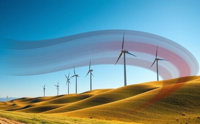
The Gansu Wind Farm in northwestern China stretches across more than 100 kilometers of desert plateau. On a clear afternoon, the wind comes off the Gobi at a steady 9 to 11 meters per second, and several thousand turbines turn in near-perfect unison. The combined output of this single installation can exceed 20,000 megawatts under good conditions. Standing at the edge of that field, watching blades the length of a commercial aircraft rotate with a kind of unhurried precision, it is easy to mistake them for simple machines. They are not. Each blade is a precision aerodynamic surface, shaped by the same physics that lifts a jet off a runway, and the engineering decisions packed into that shape determine how much of the wind’s energy ever reaches the grid.
Wind turbines succeed because they do not push against the wind. They fly through it. That distinction, between drag-based and lift-based energy extraction, is the central idea behind every modern turbine design, and understanding it opens the door to everything else about how these machines work.
Table of Contents
How a Shaped Blade Profile Generates Lift Force
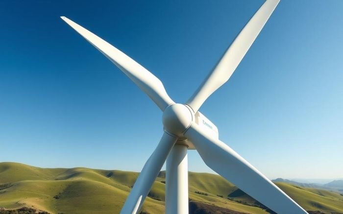
Every wind turbine blade has a cross-sectional profile called an airfoil. Cut through a blade at any point along its length and the shape you see would look like a teardrop: rounded and thick at the leading edge, tapering smoothly toward the trailing edge. This geometry is not aesthetic. It controls what happens to the air that meets it.
When wind reaches the blade’s leading edge, it divides. Air traveling over the curved upper surface must cover a longer path to reach the trailing edge than air moving along the flatter lower surface. To maintain continuity of flow without leaving a gap at the back, the air on the upper surface accelerates. Faster-moving air generates lower pressure, a relationship described by Bernoulli’s principle. The result is a persistent pressure difference: lower above, higher below. That difference pushes the blade upward and forward, which in a rotating turbine means it pushes the blade around the rotor circle. That force is lift.
Why Lift-Based Rotors Outperform Drag-Based Designs
Early windmills captured energy by letting wind push flat surfaces from behind. The force acting on them was drag. Drag-based machines face a physical ceiling: once the moving surface travels as fast as the wind, the relative velocity between them drops to zero and so does the force. An aerodynamic blade generating lift does not face this constraint in the same way. Lift acts perpendicular to the incoming airflow, so the blade can travel faster than the wind and still experience a useful force.
A well-designed turbine blade achieves a lift-to-drag ratio of around 100 to 1 at optimal conditions. For every unit of force opposing the blade’s motion, there are 100 units driving it forward. That ratio is why modern turbines can extract meaningful energy from winds that would barely disturb older drag-based designs.
Angle of Attack and the Risk of Blade Stall
The angle at which air meets the blade surface, called the angle of attack, controls how much lift is generated. Within an optimal range, typically 5 to 15 degrees for most wind turbine airfoils, lift increases steadily as the angle grows. Beyond a critical threshold, the smooth attached flow along the upper surface breaks away into chaotic separation. Lift collapses and drag spikes. This condition is called stall.
Stall is not always accidental. Older fixed-pitch turbines used deliberate stall to limit power in high winds, allowing the rotor to self-regulate without mechanical intervention. Modern variable-pitch designs treat stall as a failure state and use blade rotation to keep the angle of attack within its productive range across all wind conditions.
The Betz Limit and the Physics of Maximum Energy Extraction
A turbine cannot capture all the kinetic energy flowing through its rotor disk. If it did, the air exiting the turbine would be completely stationary, blocking any new air from entering. The machine would choke itself. Some energy must remain in the air leaving the rotor for the flow to continue.
In 1919, Albert Betz calculated the theoretical maximum fraction of wind energy any open-rotor turbine can extract. The result, known as the Betz limit, is:
Cp(max) = 16/27
Here, Cp is the power coefficient: the fraction of available wind energy converted to mechanical rotation. The value 16/27 is approximately 0.593. No turbine operating in open air can exceed this limit regardless of blade count, shape, or control strategy.
To put that ceiling in physical terms, combine it with the formula for total power available in a moving column of air:
P = 0.5 × ρ × A × v³
In this expression, P is available power in watts, ρ is air density in kilograms per cubic meter, A is the rotor swept area in square meters, and v is wind speed in meters per second. The swept area is the full circle traced by the blade tips.
Take a large offshore turbine with a rotor diameter of 164 meters. The swept area is π × 82², which equals approximately 21,124 square meters. At sea level with air density of 1.225 kg/m³ and a wind speed of 12 meters per second:
P = 0.5 × 1.225 × 21,124 × 1728 = approximately 22,400,000 watts
That is 22.4 megawatts of kinetic energy passing through the rotor disk every second. Multiply by the Betz limit of 0.593 and the theoretical maximum extraction is around 13.3 megawatts. Real turbines achieve power coefficients of 0.45 to 0.50, putting practical output closer to 10 to 11 megawatts for a machine of this size. The gap between 13.3 and 10 is where aerodynamic losses, mechanical friction, and electrical conversion inefficiency live.
How Wind Speed Dominates Power Output
The cubic relationship between wind speed and available power has consequences that are easy to underestimate. Doubling wind speed does not double available power. It multiplies it by eight. A site with an average wind speed of 8 meters per second offers only 51 percent of the energy available at a site averaging 10 meters per second, even though the wind speed difference is just 20 percent.
This is why site selection matters more than almost any other engineering decision in a wind project. A turbine performing at 80 percent aerodynamic efficiency on a mediocre wind site will produce less energy over its lifetime than a turbine at 70 percent efficiency on a strong wind site. The physics of the cubic law cannot be engineered away.
Blade Geometry: Twist, Chord, and Span-Wise Airflow
A turbine blade does not experience uniform conditions along its length. Near the hub, the blade moves slowly because it is close to the center of rotation. Near the tip, where the radius is largest, the same rotational speed produces a blade surface traveling at 80 to 100 meters per second. The angle at which wind meets the blade, the angle of attack, therefore changes continuously from root to tip.
To maintain efficient lift across the full span, blades are twisted. The root section sits at a high pitch angle to handle the low local velocity near the hub. The tip section is pitched much shallower to manage the fast-moving outer edge. Without this twist, only a narrow band of the blade would operate at an efficient angle. The rest would stall near the root or generate minimal lift near the tip.
Chord Length, Blade Taper, and Structural Tradeoffs
The chord is the width of the blade measured from leading to trailing edge. It typically decreases from root to tip, giving the blade a tapered planform. This taper is both aerodynamic and structural: wider at the root to manage the high bending loads where the blade connects to the hub, narrower at the tip to reduce the mass and inertia of the outer section.
The choice of chord length at any given point along the span is a compromise between aerodynamic efficiency and structural weight. A wider chord generates more lift but adds mass that increases centrifugal stress and fatigue loads over the rotor’s 20-year operational life.
Tip Speed Ratio and Rotor Optimization
Engineers use the tip speed ratio to describe how efficiently a rotor is operating. It is the ratio of blade tip velocity to wind speed:
TSR = (blade tip speed) / (wind speed)
A rotor with an 82-meter tip radius spinning at 10 revolutions per minute has a tip velocity of 2π × 82 × (10/60), which is approximately 85.7 meters per second. In a 12 m/s wind, the tip speed ratio is 85.7 / 12, or roughly 7.1.
Modern three-blade turbines are designed to operate between a tip speed ratio of 6 and 9. Below this range the rotor is spinning too slowly to sweep through enough air volume per second. Above it, the turbulent wake from each blade interferes with the blade behind it before it can recover clean airflow. The optimal tip speed ratio for a given design is fixed by the blade geometry, and control systems continuously adjust rotor speed and pitch to stay near this value as wind conditions change.
Everything here is free. Readers are the reason it stays that way.
I make all of it alone, with no ads. If it is worth a coffee a month to you, that keeps the next one coming.
Keep it alive →Horizontal and Vertical Axis Turbines: Two Aerodynamic Philosophies
Wind turbines split into two fundamental configurations, and their aerodynamics differ in ways that matter for where and how each type gets used.
Horizontal axis wind turbines, almost universally the choice for utility-scale power generation, point their rotors into the wind and generate lift as the blades sweep a vertical plane. They require a yaw mechanism to track shifting wind directions, but this cost is offset by their aerodynamic efficiency. At optimal tip speed ratios, horizontal axis designs can approach power coefficients of 0.50, close to the Betz ceiling.
Vertical Axis Turbines and Omnidirectional Flow
Vertical axis wind turbines orient their rotors perpendicular to the ground. Blades travel in a horizontal circle and encounter wind from any direction without the turbine needing to yaw. This makes them appealing for environments where wind shifts frequently or where the rotor needs to operate close to a surface, such as rooftops.
The aerodynamics of vertical axis designs are more complicated than they appear. As each blade completes its circular path, it passes through sectors where it is traveling with the wind and sectors where it is traveling against it. The angle of attack changes continuously through a full 360-degree rotation, making consistent lift difficult to maintain. Power coefficients for vertical axis designs typically fall in the 0.25 to 0.35 range, well below their horizontal axis counterparts.
| Feature | Horizontal Axis (HAWT) | Vertical Axis (VAWT) |
|---|---|---|
| Typical power coefficient | 0.45 – 0.50 | 0.25 – 0.35 |
| Wind direction tracking | Yaw mechanism required | Omnidirectional |
| Blade tip speed ratio | 6 – 9 | 1 – 4 |
| Best deployment context | Open terrain, offshore | Urban, complex terrain |
| Blade stall behavior | Manageable with pitch control | Cyclic, harder to control |
Factors That Reduce Aerodynamic Performance Over Time
Wind turbine blades are designed for conditions that the real atmosphere rarely delivers cleanly. Turbulence, wind shear, and blade degradation all push performance away from the theoretical optimum, and each works through a distinct physical mechanism.
Turbulence disrupts the smooth attached airflow that efficient lift depends on. When wind arrives with chaotic velocity fluctuations, the angle of attack at the blade surface shifts constantly, pushing sections of the blade in and out of their optimal operating range. Turbulence intensity of 15 percent, common in complex terrain and within wind farm wakes, can reduce power output by 5 to 10 percent compared to operation in clean laminar flow.
Leading Edge Erosion and the Degradation of Lift
Why does blade performance decline even when the control systems are working correctly?
The leading edge of a turbine blade at the tip is moving at 80 to 100 meters per second through rain, insects, airborne grit, and salt spray. Over five to ten years, this continuous bombardment roughens the smooth leading edge profile that the aerodynamic design requires. Studies of operating turbines have documented power output reductions of 5 to 15 percent attributable to leading edge erosion alone, with some offshore machines showing losses closer to 25 percent after a decade of operation without blade maintenance.
The degradation is aerodynamically significant because surface roughness promotes early boundary layer transition and separation. The blade effectively behaves as though it has a worse airfoil profile than the one it was built with. Some operators now apply protective coatings or undertake leading edge repairs every three to five years to recover lost output.
Applications of Wind Energy Across Generation Scales
Wind turbines operate across an enormous range of scales, from machines smaller than a dining table to rotors wider than the wingspan of two commercial aircraft side by side. The aerodynamic principles are the same, but the engineering context differs substantially.
Utility-scale wind farms, whether onshore or offshore, use turbines in the 4 to 15 megawatt range. A single 15-megawatt offshore turbine with a 240-meter rotor diameter can supply enough electricity for approximately 15,000 European households annually under average wind conditions. These machines justify the cost of advanced blade aerodynamics, sophisticated pitch and yaw control, and ongoing maintenance programs because their output scale makes incremental efficiency gains economically meaningful.
Small-Scale Turbines and the Aerodynamics of Low Reynolds Number Flow
Small turbines for residential or remote power supply operate in a regime where the aerodynamics behave differently. Reynolds number, a dimensionless quantity that describes the ratio of inertial to viscous forces in a fluid, scales with both blade size and speed. Small slow blades operate at low Reynolds numbers where viscous effects are stronger relative to inertial ones.
At low Reynolds numbers, the clean attached boundary layer that drives efficient lift is harder to maintain. Airfoil profiles optimized for large turbines perform poorly when scaled down. Small turbine manufacturers use different airfoil families, often with blunter leading edges and different camber distributions, specifically developed for the low Reynolds number regime. A residential turbine rated at 5 kilowatts is not simply a scaled-down utility turbine. It is a different aerodynamic machine.
Innovations Pushing Aerodynamic Efficiency Further
Blade design has advanced steadily since the 1980s, but several emerging directions are extending what aerodynamics can achieve in wind energy systems.
Active flow control systems embed small actuators, either movable flaps, suction and blowing ports, or plasma actuators, directly into the blade surface. These devices can adjust local airflow conditions in milliseconds, responding to turbulence gusts faster than any mechanical pitch system. Wind tunnel testing of active flap systems has demonstrated reductions in fatigue loads of 20 to 30 percent, which translates directly into longer blade life and the ability to build longer blades without proportionally heavier structures.
Machine Learning and Predictive Rotor Control
Traditional turbine control systems react to wind conditions as they arrive at the rotor. Lidar-based preview systems can now measure wind approaching the turbine from 200 to 300 meters upstream, giving the pitch control system several seconds of advance notice before a gust reaches the blade. When combined with machine learning models trained on months of site-specific wind data, these systems can anticipate rather than react, keeping the rotor closer to its optimal tip speed ratio for a larger fraction of operating hours.
The gains are incremental but cumulative. A turbine that maintains near-optimal aerodynamic performance 5 percent more of the time over a 20-year life generates significantly more electricity without any change to the physical machine.
Airborne Wind Energy and High-Altitude Aerodynamics
The most radical application of wind turbine aerodynamics under active development removes the tower entirely. Airborne wind energy systems use kites or tethered aircraft, flying in high-altitude winds where speeds are consistently higher and more reliable than at ground level. The aerodynamic surface, whether a rigid wing or a soft kite, generates lift that either drives a generator on the ground through a tether or carries an onboard generator and transmits electricity down a conducting cable.
Wind speeds at 500 meters altitude are typically 50 to 100 percent stronger than at 100 meters, and the cubic power law means that difference is aerodynamically enormous. The turbines currently producing most of the world’s wind electricity are optimized for the bottom 200 meters of the atmosphere. The aerodynamics of the remaining kilometers above remain largely untapped.
You read the whole thing.
That is rarer than it should be, and it is the exact kind of attention I built this archive for. I make every piece alone, with no ads and no investor deciding what gets written. If you want the next machine taken apart like this one, you can help me make it.
A coffee a month is enough to keep it free for everyone.
Prefer crypto or a one time gift? Other ways to give →
Technologies Related to This Concept
| Technology | Concept |
|---|---|
| Micro Vortex Generators for Urban Energy Harvesting | Compact devices that create small-scale vortices to capture wind energy from urban airflow. |
| Flexible Piezoelectric Strips for Window Energy Capture | Thin, flexible strips integrated into window frames to capture wind energy from passing breezes. |
| Nano Wind Turbines Embedded in Building Facades | Tiny turbines integrated into the sides of buildings to capture wind energy. |
| Bio-Inspired Fluttering Leaves Generators | Devices mimicking leaves that flutter in the wind to produce electricity. |
| Wind-Powered Helical Wind Funnels | Compact helical structures that funnel wind to drive internal generators. |
| Kinetic Energy Harvesting from Traffic-Induced Airflow | Devices placed near roads that capture energy from the airflow generated by passing vehicles. |