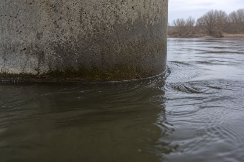
Something is already happening downstream of every bridge pier on Earth. The water splits around the column, passes it on both sides, and where it rejoins it does not simply close. It sheds. A rolling street of alternating vortices forms in the wake – one detaching from the left, then one from the right, then the left again – each spinning opposite to the last, each drifting downstream at a pace the water sets. Engineers call this a Karman vortex street. They spend considerable effort ensuring the structure does not respond to it. The famous collapse at Tacoma Narrows in 1940 was partly a lesson in what happens when a structure does respond – when the shedding frequency of wind vortices behind the bridge deck matched the structure’s natural resonance and drove it to destruction.
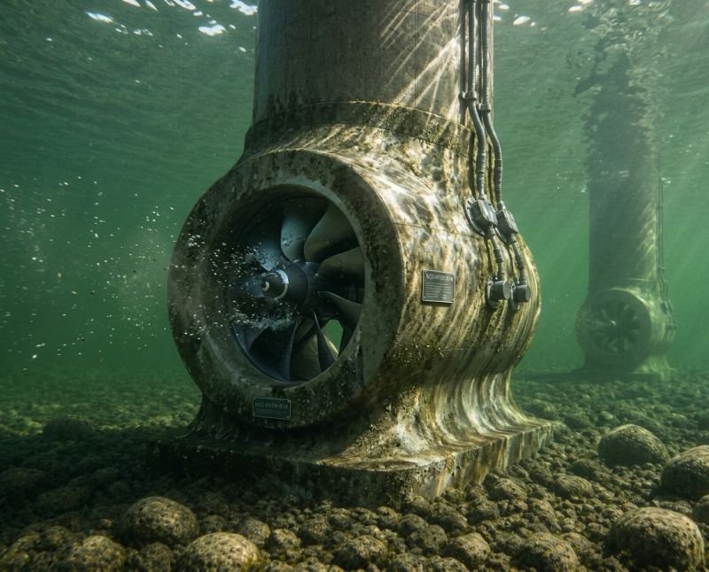
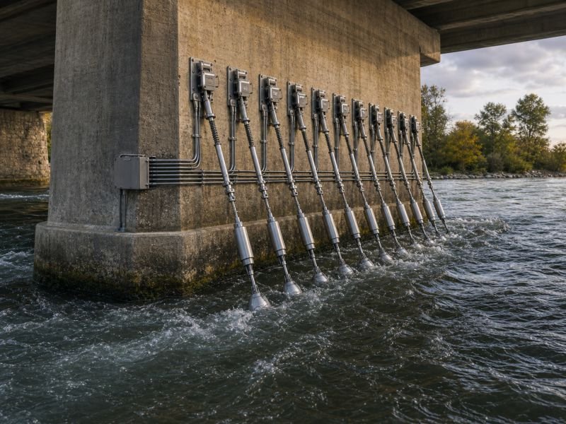
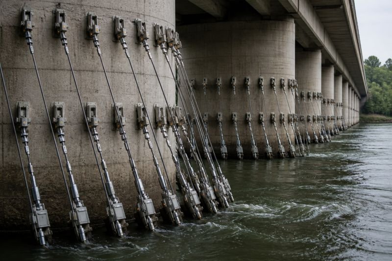
Karman vortex cables do not fight this pattern. They use it. Tensioned cables anchored downstream of existing bridge piers, sized and tuned to the frequency the column already generates, oscillate rhythmically in step with the vortex street. Piezoelectric couplings at the anchor points convert that mechanical bending into current. No turbine, no rotating parts, no modification to the pier.
The short version: Every bridge pier in a flowing river generates a continuous Karman vortex street at a frequency determined by water speed and column diameter. Tensioned cables deployed immediately downstream oscillate in phase with those vortices via a lock-in effect, and piezoelectric couplings at both anchor points convert repeated bending into electricity. At a typical river flow of 1.2 m/s, a single cable segment produces roughly 5 mW per meter of length. A bridge with twenty piers, each carrying ten five-meter cables, generates around 500 W continuously – enough to run the bridge’s sensor systems, warning lights, and structural monitoring equipment from the river it crosses.
Key Takeaways
- Karman vortex streets form behind every cylindrical pier in moving water – the oscillation is already present and costs nothing to initiate
- The shedding frequency is governed by the Strouhal number – making each cable’s resonant behavior calculable and physically tunable by adjusting cable diameter
- Piezoelectric couplings convert repeated cable bending to current with no rotating components
- Below roughly 0.4 m/s, vortex shedding becomes too irregular for lock-in; above 2 m/s, power output scales sharply upward
- The same pier geometry that makes a bridge a structural liability with respect to vortex forces becomes the cable array’s primary asset
Table of Contents
What Every Bridge Pier Does to Water
A cylindrical object in a moving fluid does not simply push water aside. At low flow speeds, the water wraps around the object and closes smoothly behind it. Past a certain velocity – once the Reynolds number climbs above roughly 40 – that smooth closure breaks. The boundary layer separates and the separated flow rolls up alternately on each side of the cylinder, producing a vortex on the left, then one on the right, then the left again, each one peeling away and drifting downstream.
The full fluid dynamics of this process are examined in Fluid Dynamics in Hydro Power. What matters here is the frequency. Because the frequency is not random – it is predictable, stable, and tied to a relationship engineers have known for over a century.
The Strouhal Relationship and the Tuning Dial
The rate at which vortices shed follows a precise formula:
f = St x V / D
Where f is the shedding frequency in Hz, St is the Strouhal number (approximately 0.2 for a smooth cylinder at typical river Reynolds numbers), V is the flow velocity in m/s, and D is the cylinder diameter in meters.
For a bridge pier 1.5 meters in diameter with water flowing at 1.2 m/s:
f = 0.2 x 1.2 / 1.5 = 0.16 Hz
One vortex shedding event every 6.25 seconds. A cable tuned to respond at 0.16 Hz is a long, loosely tensioned element – which is precisely the geometry the device requires.
For a narrower element – say a 5 cm cable attached to the pier’s downstream face – the same water speed gives:
f = 0.2 x 1.2 / 0.05 = 4.8 Hz
Every 0.2 seconds. The cable diameter is the tuning dial. Vary it and the resonant frequency shifts. A bridge with piers of a fixed diameter will see a fixed Strouhal frequency for a given flow speed, and the cable array is sized to match that number. The fact that the dial is physical – a length of cable of a particular diameter, cut and tensioned in a fitting – rather than electronic is both the device’s manufacturing simplicity and its maintenance logic. There are no software parameters to drift.
How the Device Could Operate
The cable is not simply dropped into the wake behind the pier. The geometry must be deliberate, and the lock-in mechanism is the reason the device works at all rather than simply shuddering at random.
Cable Geometry and the Lock-In Effect
When a cable’s natural frequency matches the vortex shedding frequency of the upstream column, a phenomenon called lock-in occurs. The cable stops passively receiving impulses and begins actively participating in the shedding cycle. Oscillation amplitude increases significantly – sometimes by a factor of three or more compared to the response at mismatched frequencies. The vortex street partially reorganizes around the cable’s own motion, and the two systems become coupled.
Lock-in is both the device’s primary physical advantage and the constraint that cannot be ignored. The cable must be tensioned precisely to bring its natural frequency within the lock-in range of the pier’s shedding output. Too stiff and the cable barely moves. Too loose and the oscillations are chaotic rather than rhythmic. The operational window is real but requires deliberate calibration for each deployment.
The cable runs from an anchor point on the riverbed or a low bracket on the pier to a fixing point higher on the pier’s downstream face. Tension is adjustable at the upper anchor. The cable hangs at an angle in the water, oscillating transversely – swinging side to side in the plane perpendicular to flow as successive vortices pull it alternately left and right.
The Piezoelectric Coupling at the Anchor Points
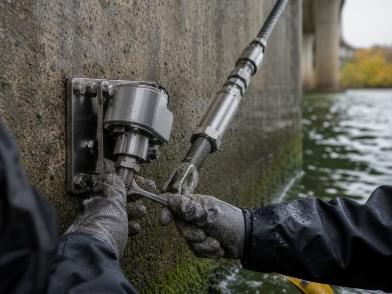
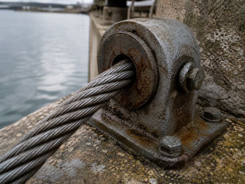
At both ends of the cable, where it meets its anchor fitting, the device installs a piezoelectric coupling – a ceramic stack or thin PVDF film element compressed into the fitting so that each side-to-side oscillation transmits a bending moment to the element. The element deforms, a voltage appears across its faces, charge accumulates, and a rectifier circuit collects it.
The conversion happens at the bending point, not along the cable’s length. For maintenance, this matters considerably: the cable itself is a passive mechanical element fully submerged. The electronics sit at the anchor fittings, at or near the waterline, accessible without diving equipment. Replacing a worn piezoelectric element means removing the fitting at the anchor bracket, not working underwater on the cable mid-span.
PVDF film elements under cyclic bending conditions convert between 15% and 30% of mechanical input to electrical output. The device makes no claim that this is high. The argument is that the mechanical input costs nothing because the vortex street would form against the pier regardless of whether cables are there to receive it.
Minimum Speed and the Dead Zone
Lock-in requires a stable, periodic vortex street. Below approximately 0.4 m/s for typical cable diameters, the Karman street behind a bridge pier becomes irregular. Vortices shed inconsistently, the cable oscillates without a dominant frequency, and lock-in cannot establish itself.
A flow velocity of 0.4 m/s is slower than most rivers where bridge construction is warranted. The dead zone exists and belongs in any deployment calculation, but it does not define what the device can or cannot do. The question is what happens above the threshold – and above it, the scaling is steep.
The Numbers Behind the String
Power output from vortex-induced vibration scales with the cube of velocity and linearly with cable length. A working estimate for a PVDF-coupled cable at 1.2 m/s is approximately 5 mW per meter of active cable length. The 5-meter cable produces roughly 25 mW continuously.
That single number is not impressive. A single LED draws more. The picture changes when the cable is considered as one element of a larger array – and when the velocity-cubed relationship is taken seriously.
| River flow (m/s) | Output per meter (mW) | 5m cable output (mW) | 200-cable bridge (W) |
|---|---|---|---|
| 0.4 | 0.2 | 1 | 0.2 |
| 0.8 | 2 | 10 | 2 |
| 1.2 | 5 | 25 | 5 |
| 1.6 | 12 | 60 | 12 |
| 2.0 | 25 | 125 | 25 |
A bridge with twenty piers, each carrying ten cables five meters long, holds two hundred cable units. At 1.2 m/s, the installation produces 5 W continuously. At 2.0 m/s it delivers 25 W. Neither figure electrifies a city. Both figures power the bridge’s own monitoring and lighting infrastructure from the river below it, without external supply or battery systems that need periodic replacement.
The velocity-cubed scaling is the device’s most significant physical property. Moving from a slow canal to a fast mountain river does not double the output. It multiplies by a factor approaching thirty. Site selection matters more than cable count – a bridge crossing a fast river with a two-hundred-cable array at 2 m/s delivers the equivalent of what a six-thousand-cable array would need to match at 0.8 m/s.
Everything here is free. Readers are the reason it stays that way.
I make all of it alone, with no ads. If it is worth a coffee a month to you, that keeps the next one coming.
Keep it alive →From One Cable to a Forest
A single cable is a proof of mechanism. The device becomes architecturally interesting when the full cable population of a bridge is considered as a single distributed system.
Wake Interaction and Spacing
When multiple cables hang in the same vortex wake, they do not all behave independently. A cable positioned close downstream of another sits partly in its predecessor’s disturbed wake – the upstream cable has already reorganized the vortex pattern the downstream one depends on. Space them too closely and downstream units underperform. Space them too far apart and the pier’s organized wake has already dissipated before the cable reaches it.
The practical spacing rule is lateral separation of roughly three cable diameters between adjacent cables in the same cross-section, with vertical staggering between cables at different depths. Each cable gets enough clear water to establish its own lock-in response while remaining within the organized Karman street from the pier. A pier two meters wide might accommodate eight to twelve well-positioned cables before the downstream wake becomes too chaotic for additional units.
Wake galloping – a more violent oscillation mode triggered when cables are positioned at specific unlucky spacing intervals – is the failure case to avoid. It produces large-amplitude swings that fatigue the cable at its anchor fittings far faster than normal lock-in oscillation. The geometry of the full array requires validation before deployment. Tuning empirically after installation is not a design strategy.
Where the Cables Could Work
Bridge piers are the natural first deployment point, but they are not the only structure in flowing water that sheds Karman vortices from cylindrical elements.
Bridges as Primary Infrastructure
The advantage of bridges is not only that they have piers. It is that they already carry electrical infrastructure – lighting circuits, camera systems, traffic sensors, emergency call points. A cable array does not need a new grid connection. It needs to supply the bridge’s own loads, and those loads are modest, predictable, and already wired to distribution points on the structure.
An array integrated during a planned maintenance cycle adds no structural modification to the pier itself. Anchor brackets mount on the downstream face with surface fixings. The cable geometry sits entirely below the navigational clearance zone. The electrical leads run up the pier face in conduit alongside existing cable routes. From the bridge operator’s perspective, the installation looks like an addition to the monitoring system, not a new energy project.
Offshore Platforms and River Monitoring Posts
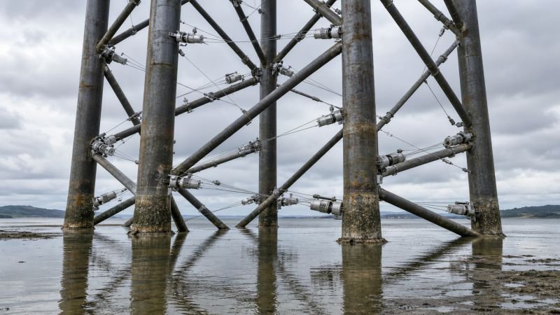
Offshore jacket platforms – the steel lattice structures used in shallow-water installations – carry multiple cylindrical members at varying angles to tidal and current flow. A platform with Karman cable housings at structural nodes harvests small amounts of power continuously from the currents moving around it, supplementing the platform’s own supply without additional active machinery.
River monitoring stations already stand in midstream on cylindrical pylons in many river systems. A cable array around a monitoring pylon turns the structure from a passive measurement post into a self-powered node. The cables that harvest energy also respond to changes in flow velocity and direction – the same oscillation pattern that drives the generator carries information about the water’s behavior.
This dual function is the more consequential long-term trajectory. A cable measuring its own oscillation frequency also measures the river’s flow velocity at that point. An array of cables across a full bridge span measures flow across the entire cross-section. The monitoring infrastructure justifies the energy harvesting, or the energy harvesting justifies the monitoring. Either direction of causality leads to the same installation.
What the Builder Must Solve
The Structural Safety Conflict
The most uncomfortable question for any bridge authority reviewing this proposal is also the most direct one: the device is designed to make a structural element of a bridge oscillate in a controlled way.
Karman vortex streets already exert oscillating lateral forces on bridge piers. The cables are designed to respond to that forcing. They also couple mechanically back to the pier through their anchor fittings, creating a two-way dynamic relationship between the cable array and the column. If the collective cable response amplifies the lateral force on the pier rather than absorbing it, the installation creates a structural problem.
The structural analysis required before any deployment must include the full coupled system – pier, cables, couplings, and anchor fittings – evaluated across the expected range of flow velocities. The goal is to confirm that the cables operate in a frequency range well separated from the pier’s own structural resonances. A cable array tuned to 0.16 Hz on a pier whose first structural mode sits at 0.8 Hz presents no issue. A cable array operating closer to the pier’s natural frequency requires redesigned cable lengths and tensions before anything goes in the water.
This constraint does not eliminate the concept. It means deployment requires pier-specific structural analysis, which adds cost and time. It also adds a consequence the bridge operator may find useful: a deployment that has cleared structural review generates ongoing data about the pier’s actual dynamic response under live loading. The monitoring the safety analysis demands becomes an operational asset after installation.
Materials and Fatigue Life
A cable in a river experiences constant mechanical fatigue. Every oscillation cycle bends the cable slightly at its anchor fittings, and the PVDF elements at those fittings experience the same cycling. At a shedding frequency of 4 Hz, an anchor fitting accumulates roughly 126 million bending cycles per year.
High-cycle fatigue design is standard engineering in aerospace and civil structures. The cable material and fitting geometry must be specified for this regime from the outset. The detail that determines operational lifespan is not the cable itself – it is the interface between cable and piezoelectric element inside the fitting. A well-designed fitting runs for twenty years. A poorly designed one fails in two, and the failure mode is not dramatic but the maintenance cost is.
The cable itself becomes a serviceable consumable: designed to be released from its anchor brackets, inspected or replaced, and reinstalled without structural work on the pier. The brackets are permanent. The cables are not.
The View From NoSuchDevice
I find the appeal of Karman vortex cables harder to articulate than the appeal of most devices on this site, because the energy numbers are genuinely small. Twenty-five watts from a full bridge installation is not an energy story in the conventional sense. Nobody is replacing a power plant with cable arrays on river crossings, and pretending otherwise would be the kind of lazy optimism the subject does not deserve.
What I find interesting is the argument the device makes about infrastructure as a usable surface. The bridge is already in the river. The pier is already generating vortex streets. The electrical infrastructure is already run. The monitoring need is already there. Karman vortex cables are not a new intervention – they are a recognition that something already happening can be redirected rather than fought or ignored.
The structural concern is real and I would not want it minimized. Getting a bridge authority to approve an installation designed to oscillate in a controlled way will require careful analysis and some patience. That is a legitimate obstacle, not bureaucratic friction.
But the dual-function argument – energy harvesting that simultaneously delivers continuous flow measurement across a bridge’s full span – changes the economics in a way that raw wattage cannot. If the cable array provides hydrological data the monitoring system currently lacks, the justification stops depending on the power output. The electricity becomes a side effect of the sensing, and the sensing stands on its own.
Whether this scales into something meaningful depends almost entirely on site velocity. On a fast mountain crossing at 3 m/s, the numbers start looking different. On a slow lowland canal, they probably never will. The interesting bridges are the ones in the middle, crossing rivers nobody is monitoring well yet.
You read the whole thing.
That is rarer than it should be, and it is the exact kind of attention I built this archive for. I make every piece alone, with no ads and no investor deciding what gets written. If you want the next machine taken apart like this one, you can help me make it.
A coffee a month is enough to keep it free for everyone.
Prefer crypto or a one time gift? Other ways to give →