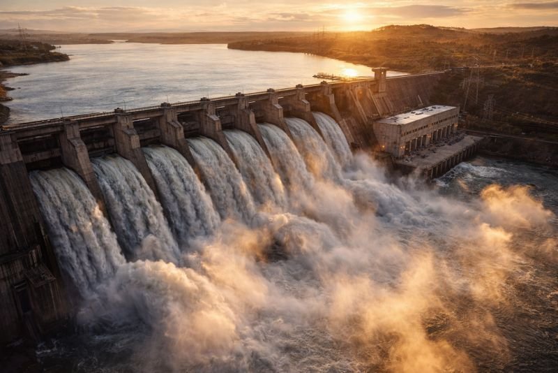
At the Bieudron hydroelectric plant in the Swiss canton of Valais, water falls from a reservoir perched 1,883 metres above the turbine hall. By the time it reaches the three Pelton wheels at the base, it is moving at roughly 190 metres per second. The pressure at the nozzle tip exceeds 180 bar. Every second, the plant converts that falling water into 1,269 megawatts of electrical output, enough to supply a city of over a million people. Nothing burns. No fuel is consumed. The entire operation depends on a single physical transaction: a moving fluid transfers its energy to a solid surface, and that surface spins a generator.
The physics governing that transaction is fluid dynamics, and it determines everything about how hydroelectric power works, how much energy a given flow can deliver, and where the engineering limits lie.
The short version: Fluid dynamics describes how water moves, exerts pressure, and transfers energy to surfaces in its path. In hydroelectric power, the kinetic and potential energy of flowing water spins a turbine, and the amount of extractable power depends on the volume of water, the height it falls, and how efficiently the turbine captures momentum. A single cubic metre of water falling 100 metres carries about 981 kilojoules of energy. Fluid dynamics sets the rules for how much of that energy a turbine can actually harvest.
Table of Contents
How Fluid Dynamics Governs Water Flow
Water behaves according to physical rules that apply whether it fills a kitchen tap or a penstock feeding a 700-megawatt turbine. Fluid dynamics describes these rules: how pressure distributes through a liquid, how velocity changes when a channel narrows, and how energy is conserved or lost as water moves from one point to another.
Continuity and Conservation of Mass in Fluid Dynamics
A fundamental constraint on any water flow is that mass cannot appear or disappear. If a river narrows, the water must speed up. If a pipe widens, the flow slows. The continuity equation captures this relationship: the product of cross-sectional area and velocity remains constant along a flow path, assuming the fluid is incompressible. Water, for practical purposes in hydroelectric systems, is incompressible.
When engineers design a penstock, the steel pipe that carries water from a reservoir to a turbine, they use the continuity principle to calculate how fast the water will be moving when it arrives. A smaller pipe means higher velocity. A larger pipe means lower velocity but less frictional loss along the walls. The balance between speed and friction is one of the first design decisions in any hydroelectric installation.
Bernoulli’s Equation and Energy Along a Streamline
The second governing relationship connects pressure, velocity, and elevation along a streamline. Bernoulli’s equation describes how energy distributes within a moving fluid. It states that the total mechanical energy per unit volume of an ideal fluid remains constant along a streamline.
The equation is:
P + 0.5pv² + pgh = constant
Here, P is the static pressure of the fluid, p is the density of water (approximately 998 kg/m³), v is the velocity, g is gravitational acceleration (9.81 m/s²), and h is the height above a reference point.
Consider water in a reservoir sitting 200 metres above a turbine. At the surface, velocity is essentially zero and the pressure is atmospheric. As the water descends through a penstock, it loses height. That lost potential energy (the pgh term) converts into kinetic energy (the 0.5pv² term) and pressure energy. By the time it reaches the turbine, the water is moving fast and carrying substantial kinetic energy.
Working through the numbers: if h drops by 200 metres and we ignore friction losses for a moment, the velocity at the turbine would be v = sqrt(2gh) = sqrt(2 x 9.81 x 200) = approximately 62.6 metres per second. That is about 225 kilometres per hour. Real systems lose some of that energy to pipe friction and turbulence, but the calculation shows how dramatically gravitational potential converts to speed.
Pressure, Head, and the Energy Budget of Fluid Dynamics
Hydroelectric engineers rarely talk about water speed. They talk about head. Head is the effective height difference between the water surface in the reservoir and the turbine, and it represents the total gravitational potential energy available per unit weight of water. Every metre of head corresponds to a specific amount of energy, and losses along the flow path reduce the usable head.
Gross Head Versus Net Head in Fluid Dynamics
Gross head is the raw elevation difference. Net head is what remains after subtracting friction losses in the penstock, entrance losses where water enters the pipe, and any bends or valves that create turbulence. A plant with 300 metres of gross head might have only 270 metres of net head after accounting for a long penstock with several bends.
Those 30 lost metres are not trivial. Each metre of head lost represents roughly 9.81 kilojoules per cubic metre of water that never reaches the turbine. Over a flow rate of 50 cubic metres per second, that lost head amounts to about 14.7 megawatts of power that dissipates as heat in the pipe walls and turbulent eddies. Engineers spend significant effort minimising these losses: smoothing pipe interiors, straightening flow paths, and sizing penstocks to keep velocities in the range of 3 to 5 metres per second where friction losses remain manageable.
Static and Dynamic Pressure in Fluid Dynamics
Fluid dynamics distinguishes between two components of pressure in a moving fluid. Static pressure acts equally in all directions and exists even when the fluid is stationary. Dynamic pressure arises from the fluid’s motion and acts in the direction of flow. The sum of the two is total pressure, and Bernoulli’s equation is essentially a statement that total pressure along a streamline stays constant in an ideal flow.
At a turbine nozzle, the goal is to convert as much static pressure as possible into dynamic pressure, producing a high-velocity jet that strikes the turbine blades with maximum kinetic energy. In a reaction turbine, the approach differs: the water remains pressurised as it passes through the runner, and both pressure and velocity contribute to energy transfer. The choice between these strategies depends on the available head and flow rate.
Turbine Types and How Fluid Dynamics Shapes Each Design
Not all water flows are the same, and fluid dynamics explains why different turbine designs exist for different conditions. The two variables that matter most are head and flow rate. High-head, low-flow sites need a turbine that extracts energy from a fast, narrow jet. Low-head, high-flow sites need a turbine that captures energy from a large, slow-moving volume of water.
| Turbine Type | Head Range | Flow Characteristics | Fluid Dynamic Principle |
|---|---|---|---|
| Pelton wheel | 300 to 1,800 m | Low flow, high-velocity jet | Impulse: momentum transfer from free jet to bucket |
| Francis turbine | 40 to 600 m | Medium flow, pressurised | Reaction: pressure and velocity both change through runner |
| Kaplan turbine | 2 to 70 m | High flow, low pressure | Reaction: axial flow with adjustable blade pitch |
| Crossflow turbine | 5 to 200 m | Variable flow, partial admission | Impulse: water passes through runner twice |
A Pelton wheel operates on the impulse principle. Water exits a nozzle as a free jet and strikes cup-shaped buckets on the wheel’s rim. The jet transfers its momentum to the buckets, and the water leaves at low velocity. The fluid dynamics here are relatively straightforward: momentum change equals force, and force times radius equals torque.
Francis turbines use a different approach entirely. Water enters a spiral casing that wraps around the runner, passes through adjustable guide vanes that control flow angle and rate, and then moves through curved runner blades where both pressure and velocity drop. The fluid dynamics are more complex because the water remains enclosed and pressurised throughout the energy transfer. Designing the blade geometry requires computational fluid dynamics simulations that model three-dimensional flow patterns, pressure distributions, and boundary layer behaviour across every surface.
Kaplan turbines sit at the opposite end of the head spectrum. Built for low-head, high-flow sites like large rivers with modest elevation changes, they resemble a ship’s propeller mounted vertically. Their blades can pivot to adjust the angle of attack as flow conditions change, maintaining efficient fluid dynamic performance across a range of water volumes that would leave a fixed-blade turbine struggling.
The Power Equation in Fluid Dynamics for Hydro Power
The fundamental equation linking fluid dynamics to electrical output is deceptively simple.
P = p x g x Q x h x n
Here, P is power in watts, p is water density (998 kg/m³), g is gravitational acceleration (9.81 m/s²), Q is the volumetric flow rate in cubic metres per second, h is the net head in metres, and n is the overall efficiency of the system, typically between 0.85 and 0.93 for modern installations.
Consider the Itaipu Dam on the border of Brazil and Paraguay. Each of its 20 generating units operates with a net head of approximately 118 metres and a flow rate of roughly 700 cubic metres per second per unit. Using the power equation:
P = 998 x 9.81 x 700 x 118 x 0.93 = approximately 752 megawatts per unit
The actual rated capacity is 700 MW per unit, which aligns well given that efficiency and exact head vary with operating conditions. Across all 20 units, the plant produces up to 14,000 MW, making it one of the largest hydroelectric installations on Earth.
What makes this equation powerful from a fluid dynamics perspective is that it shows exactly where the energy comes from. Power scales linearly with both flow rate and head. Doubling the head doubles the power. Doubling the flow doubles the power. But achieving either requires dramatically different engineering: more head means higher dams or longer penstocks with greater pressure ratings, while more flow means wider channels and larger turbines.
Everything here is free. Readers are the reason it stays that way.
I make all of it alone, with no ads. If it is worth a coffee a month to you, that keeps the next one coming.
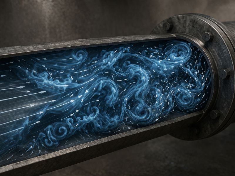
Keep it alive →Turbulence and Energy Loss in Fluid Dynamics
Every real hydroelectric system loses energy to turbulence. When water flows smoothly in parallel layers, the flow is laminar. When it becomes chaotic and irregular, with swirling eddies and rapid velocity fluctuations, it is turbulent. Almost all flows in hydroelectric systems are turbulent, and managing that turbulence is central to plant efficiency.
Reynolds Number and Flow Regime in Fluid Dynamics
Whether a flow is laminar or turbulent depends on the Reynolds number, a dimensionless quantity that compares inertial forces to viscous forces. For flow in a pipe, the Reynolds number is calculated as:
Re = (p x v x D) / mu
Here, p is density, v is velocity, D is the pipe diameter, and mu is the dynamic viscosity of the fluid. For water at 15°C, mu is approximately 0.00114 Pa·s.
In a penstock with a diameter of 4 metres carrying water at 4 metres per second:
Re = (998 x 4 x 4) / 0.00114 = approximately 14 million
Laminar flow occurs below a Reynolds number of about 2,300. At 14 million, the flow is intensely turbulent. This turbulence creates friction along the pipe walls, generates eddies that dissipate energy as heat, and introduces pressure fluctuations that must be accounted for in structural design. Penstock walls must be thick enough to handle not just the average pressure but the transient spikes caused by turbulent fluctuations and water hammer events.
Friction and Minor Losses in Fluid Dynamics
Energy dissipated by turbulence along a straight pipe section is called friction loss. Additional losses occur at bends, valves, contractions, and expansions, collectively called minor losses despite sometimes being substantial. Engineers use the Darcy-Weisbach equation and empirical loss coefficients to estimate these losses and design systems that minimise them.
Surface roughness inside the penstock matters considerably. A welded steel pipe with mill scale has a roughness of about 0.045 millimetres. Over decades of operation, corrosion and biological growth can increase this to 0.3 millimetres or more, raising friction losses and reducing net head. Regular inspection and maintenance of penstock interiors directly affects plant output and revenue.
Cavitation and Blade Damage in Fluid Dynamics
One of the most destructive phenomena in hydro turbines is cavitation. When fluid dynamics pushes the local pressure in a flowing liquid below the vapour pressure of water, tiny bubbles form. These bubbles are not filled with air. They contain water vapour, and they exist only as long as the pressure remains low. When the flow carries them into a region of higher pressure, the bubbles collapse violently. Each collapse generates a tiny, intensely focused shock wave and a microscopic jet of water that can reach velocities over 100 metres per second.
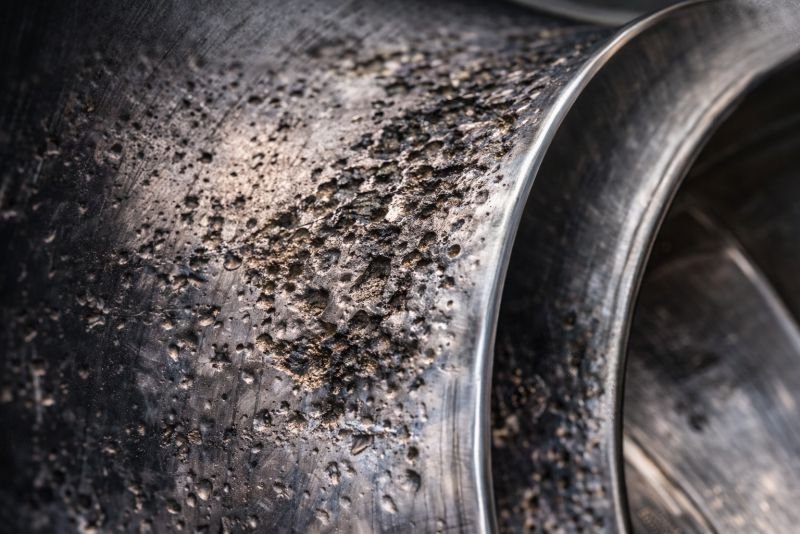
A single collapse does nothing noticeable. Millions of collapses per second, concentrated on a turbine blade surface, can erode hardened steel at rates of several millimetres per year. Cavitation pitting is one of the primary maintenance challenges in hydroelectric plants, particularly those operating Francis and Kaplan turbines where the pressure changes through the runner are large and rapid.
How do engineers prevent cavitation? The primary strategy involves controlling the pressure distribution across the turbine blades through careful geometric design. Runner blades are shaped so that the local pressure never drops below the vapour pressure threshold, approximately 1.7 kilopascals for water at 15°C. The draft tube below the runner also plays a critical role: it gradually decelerates the exiting water and recovers pressure, preventing the low-pressure zone at the runner exit from reaching cavitation conditions.
When prevention fails, the consequences are expensive. Repairing cavitation damage on a large Francis turbine runner can require weeks of downtime and hundreds of thousands of dollars in welding and grinding work. Some operators apply cavitation-resistant coatings or use stainless steel overlays on vulnerable blade surfaces, trading higher upfront cost for longer intervals between repairs.
Open Questions in Fluid Dynamics for Future Hydro Power
Computational fluid dynamics has transformed turbine design over the past three decades, but several challenges remain at the frontiers of the field. Predicting the exact onset and severity of cavitation in complex three-dimensional flows is still difficult. Turbulence modelling relies on approximations, and the most accurate simulation methods require computational resources that make full-plant simulations impractical for routine design work.
Variable-speed turbines represent one area where fluid dynamics research may unlock significant gains. Conventional turbines operate at a fixed rotational speed synchronised to the electrical grid frequency. At flow rates above or below the design point, efficiency drops because the fluid dynamics of the interaction between water and blades is optimised for only one specific condition. Variable-speed operation would allow the turbine to adjust its rotation to match changing flow conditions, maintaining optimal fluid dynamic performance across a wider operating range. Several research installations are testing this approach, though power electronics and grid integration challenges remain.
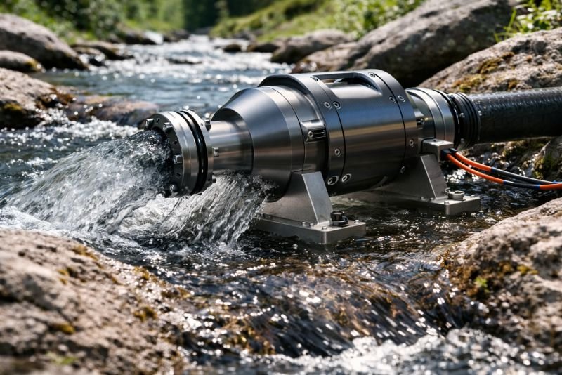
Small-scale and micro-hydro installations also present fluid dynamics problems that differ from large plants. At lower Reynolds numbers and smaller physical scales, the relative importance of viscous losses increases. Turbine designs that work efficiently at 500 megawatts may perform poorly at 50 kilowatts because the fluid dynamics scale differently. Developing high-efficiency turbines for the micro-hydro range, sites producing under 100 kilowatts, could bring reliable electricity to thousands of remote communities worldwide that sit near streams and small rivers with modest but consistent flow.
Then there is sediment. Rivers carry particles of sand, silt, and gravel, and these particles pass through turbines alongside the water. In glacially fed rivers like those in Nepal and northern India, sediment concentrations can be extreme. The particles scour blade surfaces through a process distinct from cavitation but equally damaging. Understanding how sediment-laden flows behave inside a turbine runner, and designing blade geometries that minimise erosion while maintaining hydraulic efficiency, remains one of the harder open problems in applied fluid dynamics.
You read the whole thing.
That is rarer than it should be, and it is the exact kind of attention I built this archive for. I make every piece alone, with no ads and no investor deciding what gets written. If you want the next machine taken apart like this one, you can help me make it.
A coffee a month is enough to keep it free for everyone.
Prefer crypto or a one time gift? Other ways to give →
Technologies Related to This Concept
| Technology | Concept |
|---|---|
| Harnessing River Currents: A New Frontier in Urban Energy | Concept: Exploring how urban rivers can be utilized to generate hydrokinetic power. |
| Tidal Energy in Coastal Cities: Powering Urban Areas with Ocean Tides | Concept: Utilizing tidal movements to generate electricity for coastal cities. |
| Turbine Arrays: Maximizing Energy in Limited Space | Concept: Configuring multiple turbines for optimal output. |
| Fish-Friendly Turbine Designs for Urban Rivers | Concept: Turbines that minimize harm to aquatic life. |
| Retrofitting Dams and Locks for Hydrokinetic Power | Concept: Updating existing structures to include hydrokinetic technology. |